Rockwell Automation Publication 750-IN020D-EN-P - May 2017 43
PowerFlex 755 IP00, NEMA/UL Open Type Drive
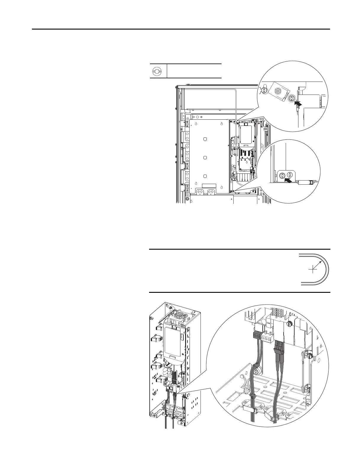
4. Swing the Control Pod into the converter assembly and tighten the captive
screws on the back panel.
5. Insert the two position connector of the single-bay 24V wire harness into
terminal P14 on the Fiber Interface Board.
6. Connect one end the fiber-optic cable to P1 (INV1) on the Fiber Interface
Board.
Minimum inside bend radius for fiber-optic cable is
50 mm (2 in.). Any bends with a shorter inside
radius can permanently damage the fiber-optic
cable. Signal attenuation increases as inside bend
radius is decreased.
T20 or F - 6.4 mm (0.25 in.)
1.8 N•m (16 lb•in)
P1
INV1
P2
INV2
P3
INV3
P14
P13
 Loading...


