44 Rockwell Automation Publication 750-IN020D-EN-P - May 2017
PowerFlex 755 IP00, NEMA/UL Open Type Drive
Fiber Interface Board Connections
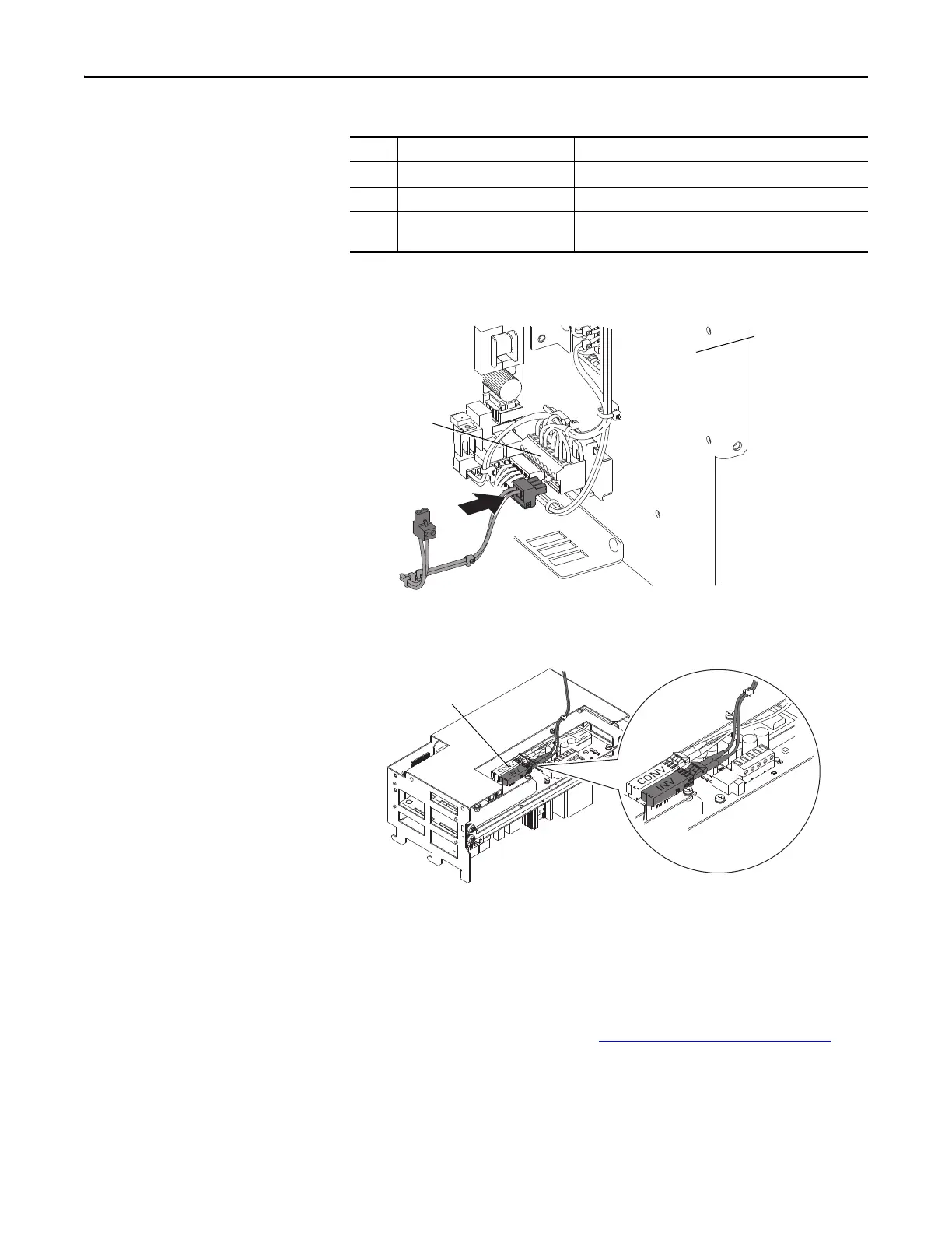
7. Insert the other end of the 24V wire harness into the converter terminal
block TB1, mounted on the converter control panel right side wall.
8. Connect the other end of the fiber cable to INV on the Power Layer
Interface Board in the inverter card cage. Excess cable length can be coiled
on the bottom of the Control Pod.
9. Replace the Control Pod Cover.
Optional External Power Supply
An external power source supplies control power to the drive when the drive is
not energized. Connect an optional external 24V power supply to P13 using the
three position connector supplied. See External Power Supply Connections
on
the next page.
No. Name Description
1 Internal 24V Power Connection Connects between P14 and TB1
2 Optional 24V Connection User supplied External 24V Power Source (see below)
3 Inverter Fiber-optic Connection Fiber-optic cable between P1 (fiber-optic transceiver INV1) and
Power Layer Interface Board
TB1
TB1
Converter
Right Side
Wall
Power Layer
Interface Board
to P1 (INV1) on Fiber
Interface Board
 Loading...


