Rockwell Automation Publication 750-IN020D-EN-P - May 2017 61
PowerFlex 755 IP00, NEMA/UL Open Type Drive
Terminal Block Specifications
TB1 Terminal Designations
Hardware Enable Circuitry
Digital Input 0 can be used as a general purpose programmable input, or by
removal of a jumper, configured as a dedicated hardware enable, which is
unaffected by parameter settings.
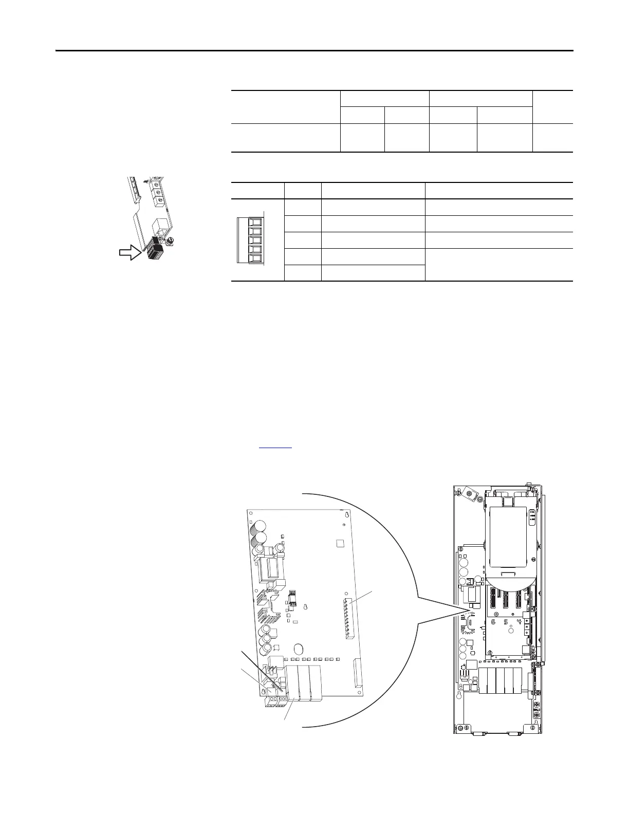
To configure Digital Input 0 as a dedicated hardware enable, complete the
following steps.
1. Access the Control Pod.
2. Locate and remove the ENABLE Jumper on the Main Control Board (see
page 60
).
Fiber Interface Board
Name
Wire Size Range Torque
Strip
LengthMaximum Minimum Maximum Recommended
Main Control Board - TB1 2.5 mm
2
(14 AWG)
0.3 mm
2
(28 AWG)
0.25 N•m
(2.2 lb•in)
0.2 N•m
(1.8 lb•in)
6 mm
(0.24 in.)
Fixed I/O Terminal Name Description
Di 0ac Digital Input 0 (120V AC) Connections for AC power supply.
Di C Digital Input Common Digital input common
Di 0dc Digital Input 0 (24V DC) Connections for DC power supply.
+24V +24 Volt Power Connections for drive supplied 24V power. 150
mA maximum
24VC 24 Volt Common
P1 P2 P3
 Loading...


