62 Rockwell Automation Publication 750-IN020D-EN-P - May 2017
PowerFlex 755 IP00, NEMA/UL Open Type Drive
Fiber Interface Board Details
Terminal Block Specifications
P13 Terminal Designations
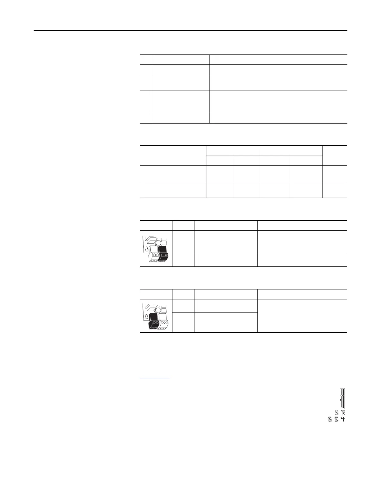
P14 Terminal Designations
Option Modules
For a complete listing and description of all available Option Modules, see the
PowerFlex 750-Series AC Drives Installation Instructions, publication
750-IN001
.
Compatible port locations may be restricted for each option module.
An icon with position number(s) is provided to indicate which module
ports are compatible. For example, the icon to the right indicates that
the option module is only compatible with port 4.
No. Name Description
1 Main Control Board Connector 98 pin main control board interface connection.
2 P13 Connections for user-supplied 24 volt power.
Powers control circuits when main power is removed.
3 P14 Connections for internal drive-supplied 24 volt power. Connection is factory
wired and must not be modified by the user. Powers control circuits when
main power is connected.
4 Inverter Connections Fiber optic ports: P1 = INV1, P2 = INV2, P3 = INV3
Name
Wire Size Range Torque
Strip
LengthMaximum Minimum Maximum Recommended
Fiber Interface Connector P13 4.0 mm
2
(12 AWG)
0.25 mm
2
(24 AWG)
0.5 N•m
(4.4 lb•in)
0.4 N•m
(3.5 lb•in)
7 mm
(0.28 in.)
Fiber Interface Connector P14 2.5 mm
2
(14 AWG)
0.3 mm
2
(28 AWG)
0.25 N•m
(2.2 lb•in)
0.2 N•m
(1.8 lb•in)
6 mm
(0.24 in.)
Power Block Terminal Name Description
AP+ +24 Volt Auxiliary Power Connections for customer supplied power supply:
24V DC ±10%, 5 A, PELV (Protective Extra Low
Voltage) or SELV (Safety Extra Low Voltage)
AP– Auxiliary Power Common
Sh Shield Terminating point for wire shields.
Power Block Terminal Name Description
1 +24 Volt Power Connections for drive supplied power.
2 Power Common
 Loading...


