40 Rockwell Automation Publication 1420-UM001E-EN-P - March 2016
Chapter 4 Communication
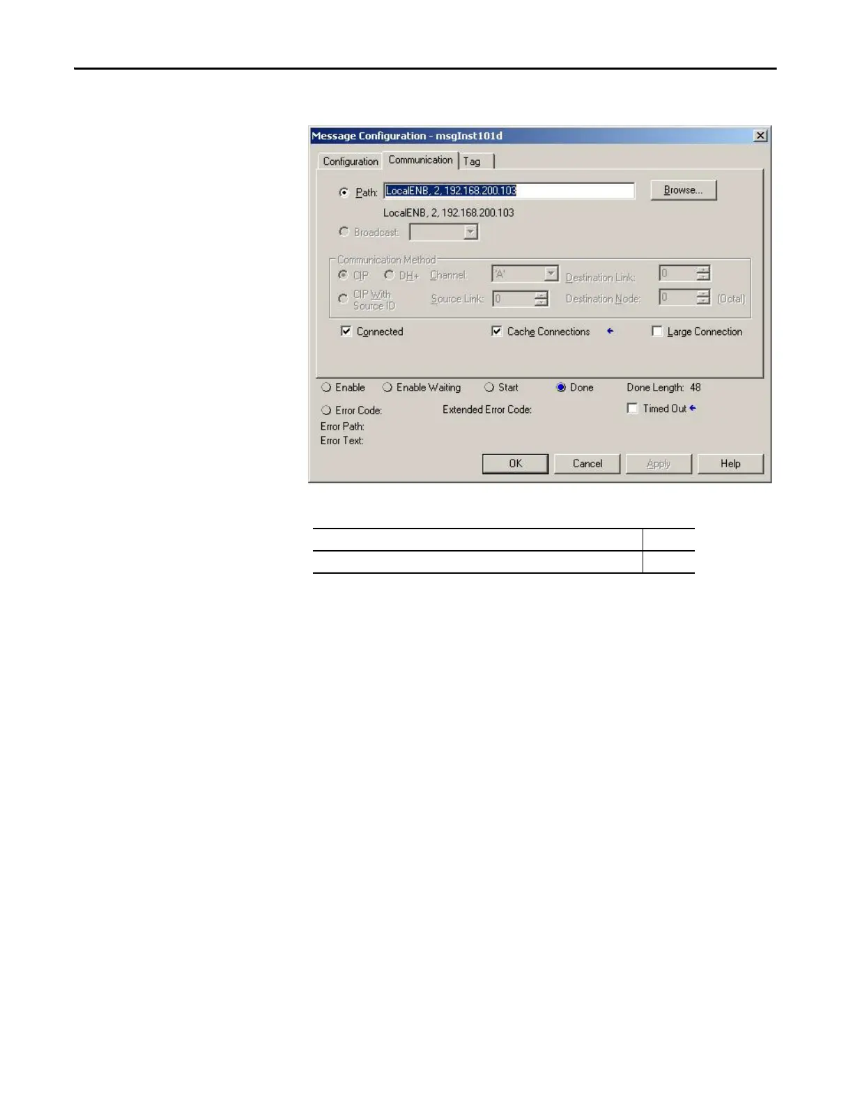
2. Click the Communication tab and enter the path and method.
3. Click OK to complete message setup.
Implicit Messaging - Generic Ethernet Module Input Data Connection
The PowerMonitor 500 unit with EtherNet/IP communication supports Class 1
connections to its nine Assembly Instances. To configure a Class 1 connection to
a selected Assembly Instance with a Logix controller, follow these steps.
1. Open the controller program offline in the Logix Designer application (or
online in Program mode if you are using a ControlLogix® controller).
2. In the I/O configuration tree, right-click the Ethernet communication
module (for example, 1756-EN2T), and choose New Module.
3. From the Communication pull-down menu, choose ETHERNET-
MODULE Generic Ethernet Module.
Path Method
<Ethernet Module, Port (always 2 for Ethernet), Power Monitor IP Address> CIP

 Loading...