Publication 2711-UM014B-EN-P
Terminal Overview 1-11
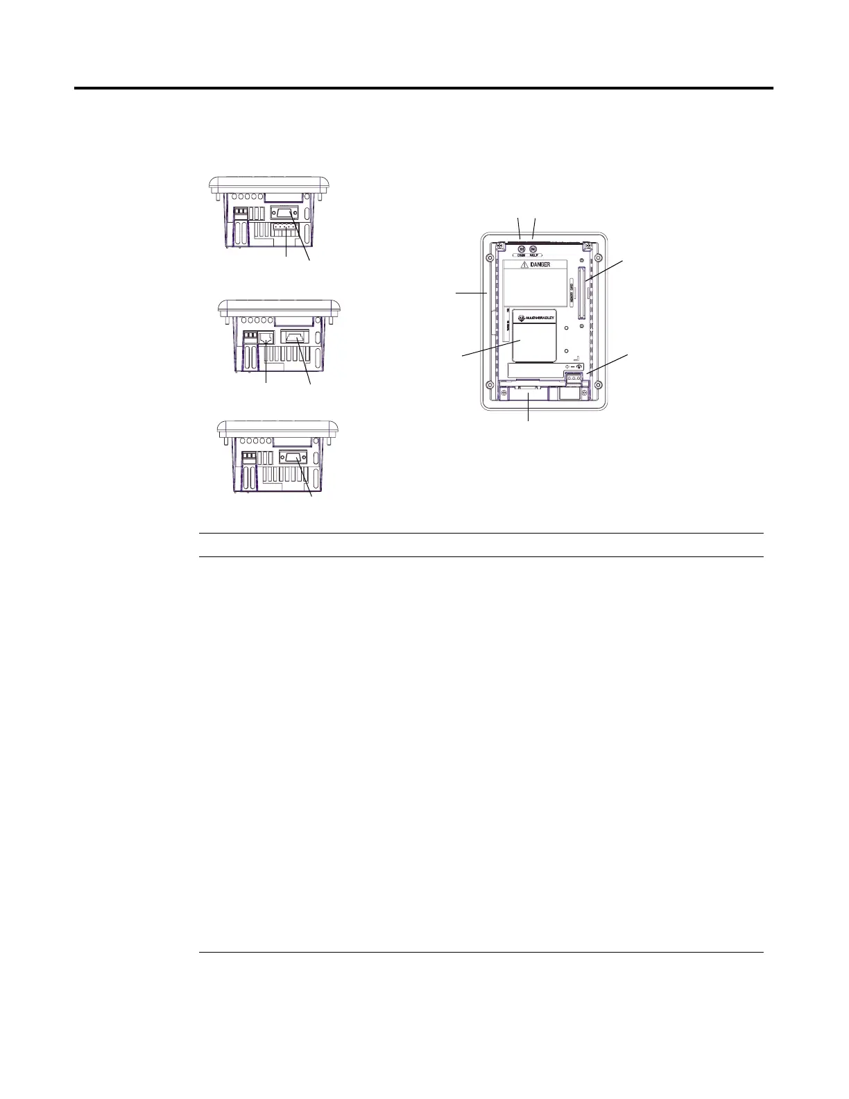
PanelView 300 Features (Back)
DH-485 without RS-232 Port
10
12
1
2
3
4
7, 8, 9, 10, 11, 12
DeviceNet with additional RS-232 Port
6
5
87
RS-232 (DH-485 or DF1) without additional RS-232 Port
9 or 11
# Feature Description
1 Nameplate Label Provides product information.
2 Sealing Gasket Seals the front of the terminal to an enclosure or panel.
3 COMM LED (Green) Indicates when communications is occurring.
4 FAULT LED (Red) Indicates firmware or hardware faults.
5 Memory Card Slot Accepts a memory card which stores applications.
6 Power Connection Terminals Connects to an external 24V dc power source (18-32V dc).
7 DH-485 Communication Port Connects to an SLC or MicroLogix controller, DH-485 network, or
Wallmount Power Supply (Cat. No. 1747-NP1).
8 DH-485
Programming Connector
Connects to a Personal Computer Interface Converter (Cat. No. 1747-PIC)
for transferring applications. Also connects to an SLC programmer, such
as the Hand-Held Terminal (Cat. No. 1747-PT1).
9 RS-232 (DH-485)
Communication Port
Connects to the Channel 0 port of an SLC 5/03, 5/04 or 5/05 controller for
point-to-point DH-485 communications. Connects to a MicroLogix
controller through an AIC+ Link Coupler. Also connects to the RS-232
serial port of a computer for transferring applications.
10 DeviceNet Connector Connects to a DeviceNet network.
11 RS-232 (DF1)
Communication Port
Connects to a PLC, SLC or MicroLogix controller with a DF1 port. This port
also connects to the RS-232 port of a computer.
12 RS-232 Printer/
File Transfer Port
Connects to a printer (K3A10L1 version only).
On a DeviceNet terminal, this port also connects to the RS-232 port of a
computer for transferring applications.
 Loading...