10 Rockwell Automation Publication 150-QS003E-EN-P - April 2017
Chapter 1 Installation
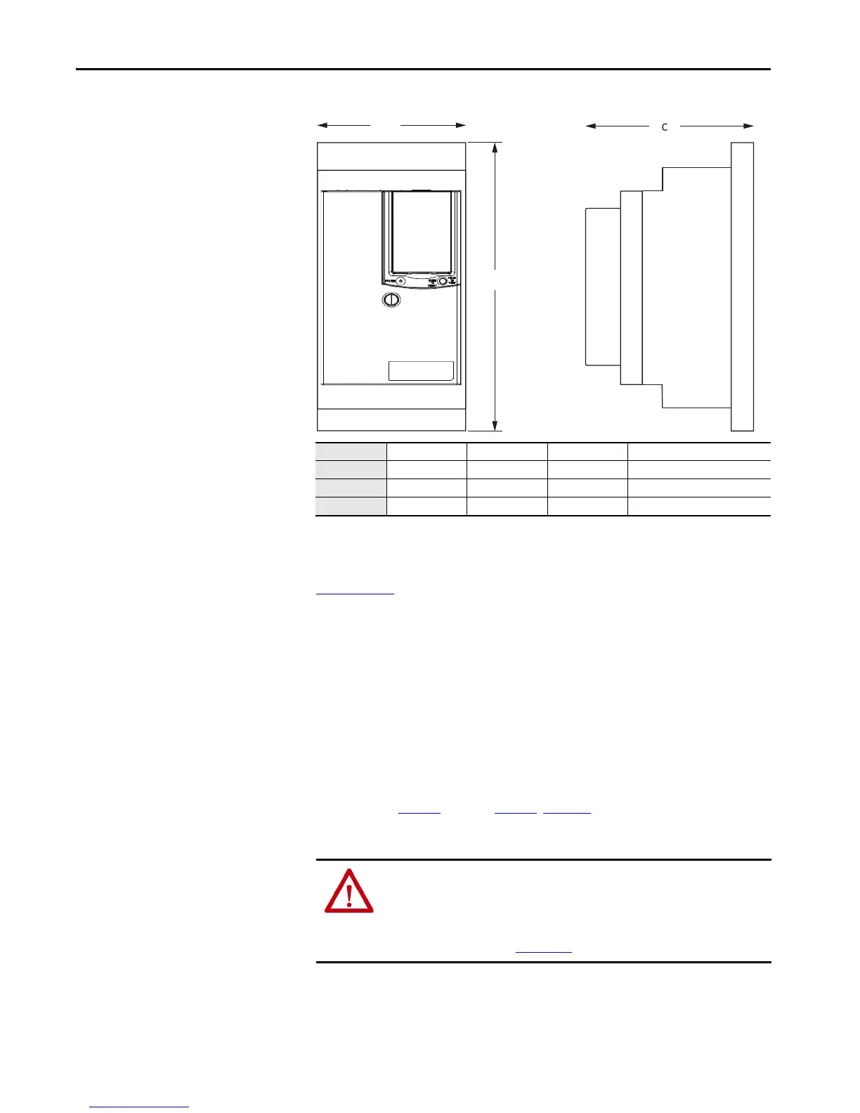
Figure 3 - Solid-state SMC-50 Soft Starter
Power Wiring
See the product nameplate or the SMC-50 controller user manual, publication
150-UM011,
for device-specific information.
SMC-50 controller power structures use solid-state SCR designs that are
capable of interfacing with 200...480V AC or 200...690V AC (690V line and
600V inside-the-delta) motors. Both the internally bypassed and solid-state
power structures are available. Verify ratings of unit before application.
The power structure incorporates three-phase true current-sensing and
overtemperature protection. You can use an external bypass contactor if it is
required for your application.
Conductor range, torque, lug, and delta distribution block lug kit information
is provided in Table 3
through Tab l e 6. Figure 4 supplies typical power wiring
diagrams.
Cat. No. Height (B) Width (A) Depth (C) Approximate Shipping Weight
150-SB… 396.6 (15.62) 194.4 (7.65) 259.2 (10.21) 15.7 kg (34.6 lb)
150-SC… 638.5 (25.14) 273.1 (10.75) 272.9 (10.75) 47.6 kg (105 lb)
150-SD… 692.2 (27.25) 457.2 (18.00) 295.8 (11.64) 77.1 kg (170 lb)
ATTENTION: SMC-50 controllers can be installed in a system with power
factor correction capacitors (PFCCs). The PFCCs must only be on the line side
of the controller. Placing the PFCCs on the load side of the SMC results in
damage to the SCRs in the SMC-50 controller. For additional details, see the
user manual, publication 150-UM011
.

 Loading...


