12 Rockwell Automation Publication 150-QS003E-EN-P - April 2017
Chapter 1 Installation
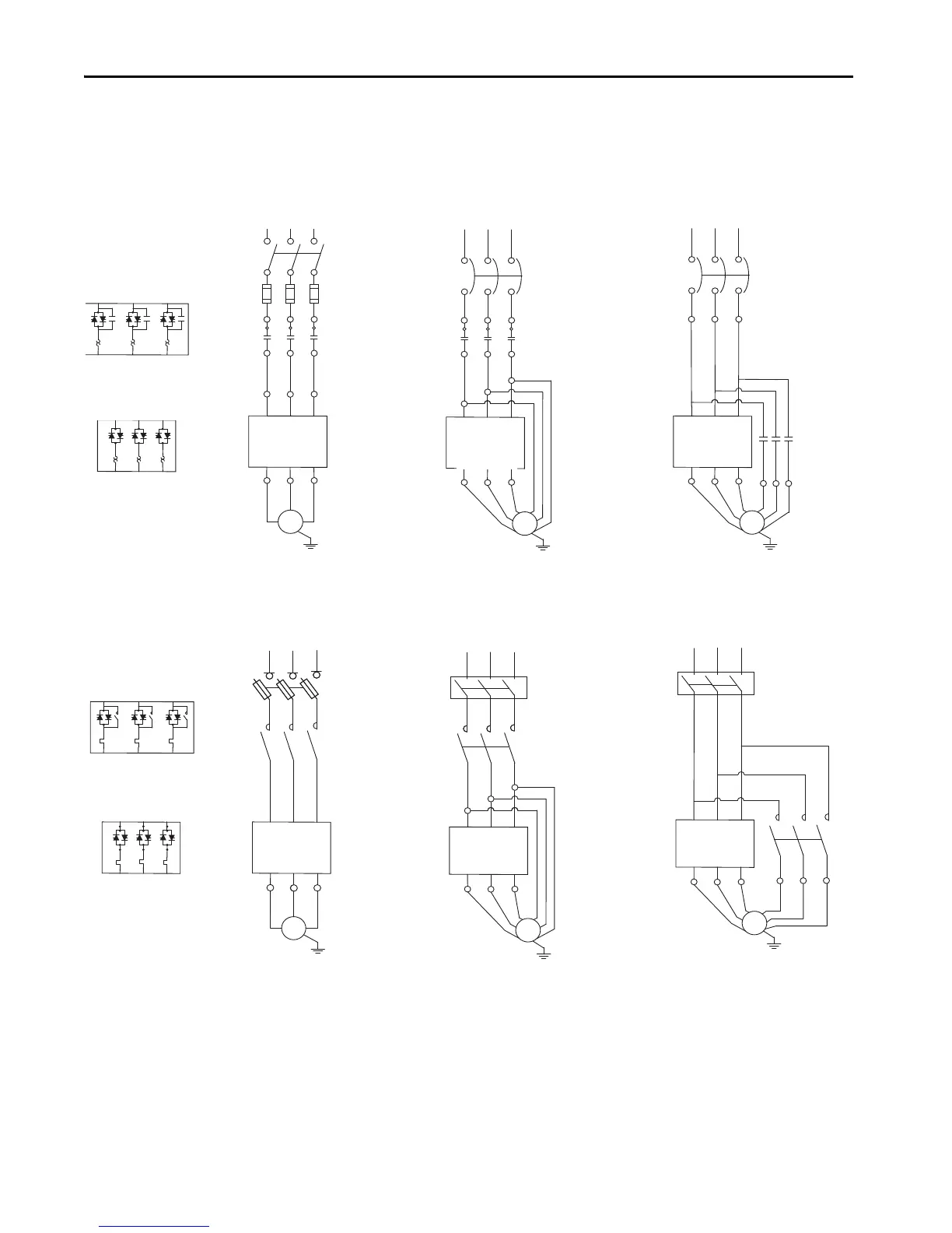
Typical Power Diagrams
Figure 4 - Power Wiring Diagrams
(1) Contactor must be fully rated for motor Hp/kW and FLA.
(2) For North American applications, size the contactor per the motor Hp and FLA. For IEC applications, size the contactor per the
motor AC-1 or AC-3 rating. The short-circuit rating of the contactor must be similar to that of the SMC-50.
T1 T2 T3
K1
L1 L2 L3
K1
L1 L2
L3
T4
T5
L1
L2
L3
K1
T1
T2 T3
T4
T5
T6
L1 L2 L3
1
35
2 4
6
1
35
2
4
6
W
1
U
1
1
35
L1 L2 L3
1
35
2 4
6
1
35
2 4
6
K1
W
2
U
2
V
2
L1 L2 L3
1
35
1
35
2 4
6
2 4
6
1
35
4
V
6
W
2
U
K1
V
1
2
4
6
W
1
U
1
V
1
2 4
6
WU
V
K1
1
35
22
2
T1
T2 T3
T6
Diagrams per NEMA Symbology
SMC-50 solid-state
controller
SMC-50 controller
with internal bypass
SMC-50 solid-state
controller
SMC-50 controller
with internal bypass
Diagrams per IEC Symbology
SMC-50
controller
SMC-50
controller
SMC-50
controller
SMC-50
controller
SMC-50
controller
SMC-50
controller
Line connection with
isolation contactor
(default mode)
Line connection with
isolation contactor
(default mode)
Inside-the-Delta connection
with isolation contactor
(optional mode)
Inside-the-Delta connection
with isolation contactor
(optional mode)
Delta connection with
shorted SCR protection
(optional mode)
Delta connection with
shorted SCR protection
(optional mode)
Motor
Motor
Motor
3~
Motor
3~
Motor
3~
Motor
(1)
(1)
(2)
(1)
(1)
(2)

 Loading...


