Rockwell Automation Publication 150-QS003E-EN-P - April 2017 17
Installation Chapter 1
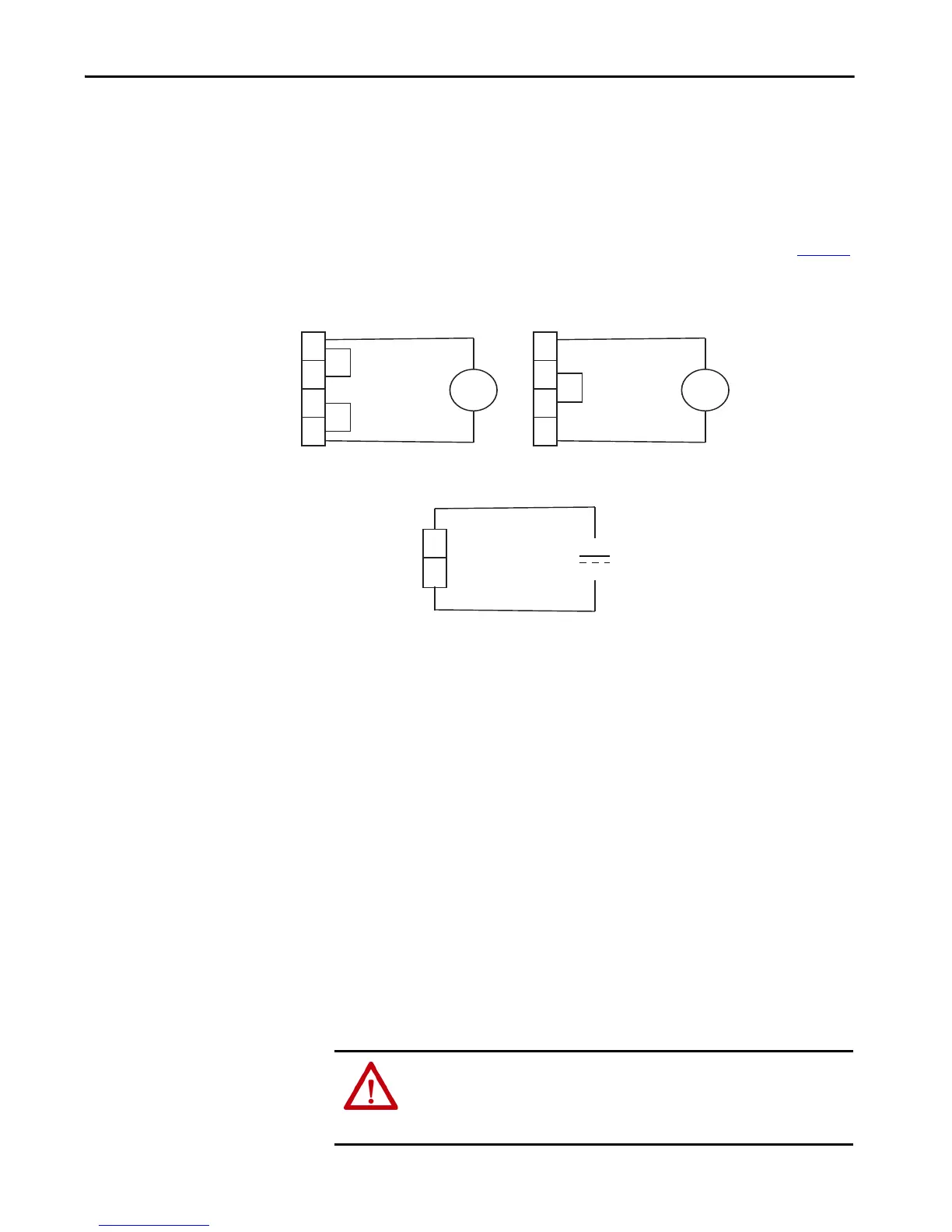
Fan Wiring
Fans for the SMC-50 controllers should be wired according to the instructions
in this section.
Integrated Bypass Units
For units with integrated bypass, you should wire the fans as shown in Figure 8.
Figure 8 - Fan Wiring—Integrated Bypass Units
Solid-state Units
Solid-state units do not require any additional wiring. The fans are connected
internally.
Upgraded Units
For SMC Flex controller-to-SMC-50 controller control upgrades, the fans
remain connected as they were in the SMC Flex controller. You do not need to
change any wiring.
Option Modules
SMC-50 controllers have three expansion ports. These ports provide the
capability to add optional modules (additional inputs and outputs (I/O),
simple start/stop parameter configuration capability, ground fault, etc.).
• Note: the 20-COMM-X communication modules can only reside in Port 9.
1
4
3
2
~
1
4
3
2
~
—
+
120V AC (Factory Set)
240V AC (Optional)
24V DC
120V AC,
1-phase
240V AC,
1-phase
24V DC
Using 150-SCMD Module
(120…240V AC Control)
Using 150-SCMR Module
(24V DC Control)
Using 150-SCMD Module
(120…240V AC Control)
ATTENTION: There is the potential to have voltage values above 220V AC on the
option modules. Before removing the control module cover to access option
modules, disconnect ALL power to the SMC-50 controller. Do not remove or add
option modules while power is applied.

 Loading...


