18 Rockwell Automation Publication 150-QS003E-EN-P - April 2017
Chapter 1 Installation
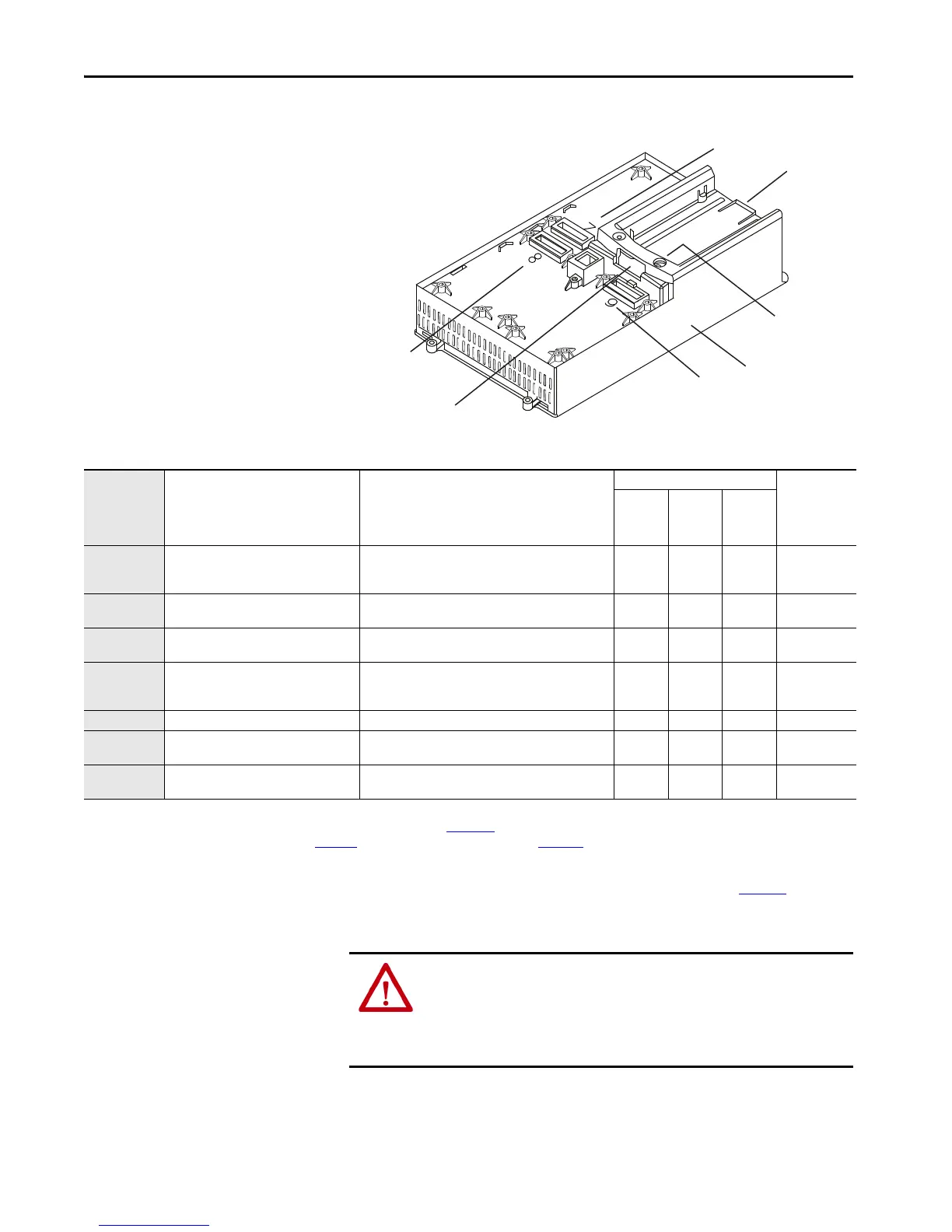
Figure 9 - Port Number Identification
Table 8 - Port Location for Compatible Option Modules
Port 7
Port 8
Port 9
HIM Bezel
HIM Port
SMC-50 control module
(shown without cover)
Port 4
Option Module
Cat. No.
Module Name Description
Compatible Control Module Port Max. No of this
Type of Option
Module per
Control
Module
Port 7 Port 8 Port 9
150-SM2
PTC, Ground Fault
(1)
and Current
Transformer Interface
• Connectivity to motor PTC sensors
• Connectivity to external ground fault sensors
(2)
• Connectivity to external current sensors
(2)
Yes Ye s N o 1
150-SM3 Analog I/O
• 2 analog inputs
• 2 analog outputs
Yes Ye s Ye s 3
150-SM4 Digital I/O
• 4 digital inputs
• 3 relay outputs
Yes Ye s Ye s 3
150-SM6 Parameter Configuration Module
• Three sets of 8-position DIP switches and five sets of
16-position rotary switches use for simple
programming.
Yes Ye s Ye s 1
20-COMM-X
(3)(4)
Communication Modules • Various communication modules are available No No Yes 1
20-HIM-A6 Enhanced, LCD display, full numeric keypad
• Can be installed on control module in bezel/cradle (DPI
Port 1) or connected with cable to DPI Port 2.
——— 1
(5)
20-HIM-C6S
Remote (panel mount), LCD display, full
numeric keypad
• Typically door- or panel mounted and connected with
cable to DPI Port 2.
——— 1
(5)
(1) The ground fault sensing feature of the SMC-50 controller is intended for monitoring purposes only.
(2) External components may be needed. See the SMC-50 controller user manual, publication 150-UM011,
for additional information.
(3) See the SMC-50 Controller selection guide, publication 150-SG010
, or SMC-50 controller user manual, publication 150-UM011, for a list of compatible 20-COMM-X communication modules.
(4) When installed in an SMC-50 controller, 20-COMM-X modules physically reside in the space assigned to Port 9, but connect to DPI Port 4 with a ribbon cable that is supplied with the communications
module.
(5) For most systems, a single HIM device is used. You can use multiple HIMs by using DPI Port 2 and a DPI Port-Splitter See the SMC-50 controller user manual, publication 150-UM011,
for additional
information.
ATTENTION: The ground fault sensing feature of the SMC-50 controller is
intended for monitoring purposes only and not as a ground fault circuit
interrupter for personnel protection as defined in Article 100 of the NEC. The
ground fault sensing feature has not been evaluated for conformance to
UL 1053.

 Loading...


