14 Rockwell Automation Publication 150-QS003E-EN-P - April 2017
Chapter 1 Installation
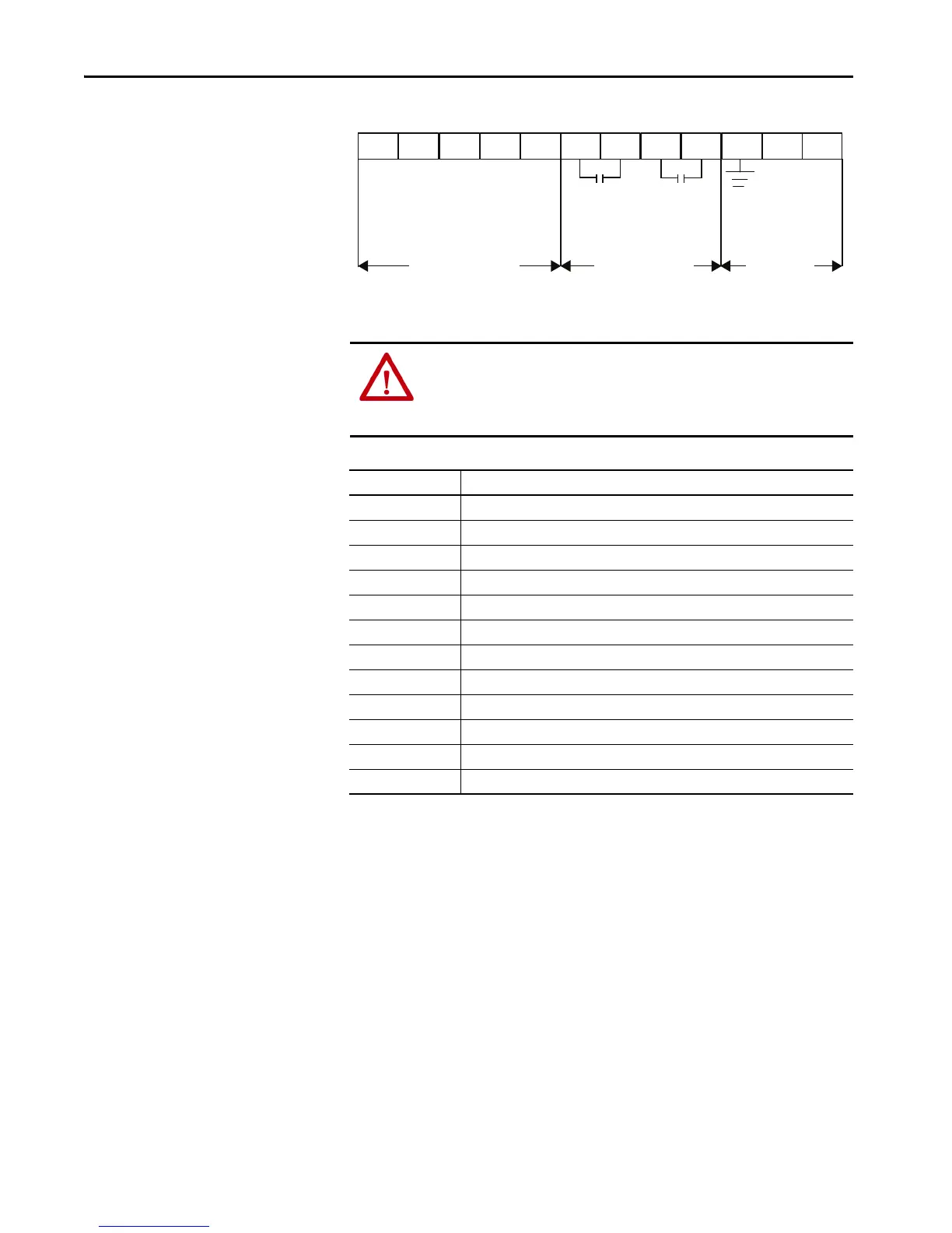
Figure 5 - Standard Control Terminal Block Identification
(1) See the controller nameplate to verify the control power ratings (120/240V AC or 24V DC).
ATTENTION: IN1 DC (terminal 11) and IN2 DC (terminal 10) are 24V DC
inputs on controllers rated 120/240V AC and on controllers rated 24V DC.
Voltages that exceed the specified input range may cause damage to the
controller.
Terminal Number Description
1
(1)
(2)
(1) RC snubbers are required when inductive loads are connected to terminal.
(2) See the controller nameplate to verify the control power ratings (120/240V AC or 24V DC)
Control Power +L1
2
(1)(2)
Control Power Common -L2
3 Ground — To connect to the system/control ground point.
4
(1)(3)
(3) When set to external bypass mode, the auxiliary contact is used to control a properly sized external contactor and overload once
the motor is at full speed.
Auxiliary Relay Contact #1—rated 3 A @ 120V AC, 1.5 A @ 240V AC
5
(1)(3)
Auxiliary Relay Contact #1—rated 3 A @ 120V AC, 1.5 A @ 240V AC
6
(1)(3)
Auxiliary Relay Contact #2—rated 3 A @ 120V AC, 1.5 A @ 240V AC
7
(1)(3)
Auxiliary Relay Contact #2—rated 3 A @ 120V AC, 1.5 A @ 240V AC
8 DC Internal I/O Power, DC Common
9 Enable I/O
10
(1)(4)
(4) Do not connect any additional loads to this terminal. Parasitic loads may cause problems with operation.
Input #2 (24V DC) (range 15…30V DC)
11
(1)(4)
Input #1 (24V DC) (range 15…30V DC)
12 +24V DC Internal I/O Power
-L2
+L1
12
11
10 9
8
7
65
4
32
1
24V DC Inputs
Relay Outputs
Control Power
and Ground
(1)
Internal +24V DC
In1 DC
In2 DC
Enable I/O
Internal DC Common
Aux 2
Aux 1

 Loading...


