Rockwell Automation Publication 150-QS003E-EN-P - April 2017 21
Installation Chapter 1
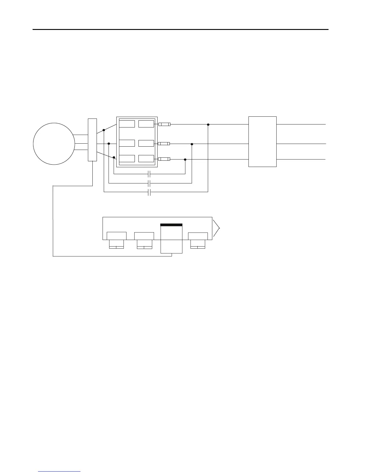
Bypass Contactor with Converter Module and Cat. No. 150-SM2 Option Module
All SMC-50 controllers, regardless of power structure, can use an external
bypass contactor with a Bulletin 825 converter module and cat. no. 150-SM2
option module. These components allow the SMC-50 controller to perform
the overload function.
Figure 11 - Wiring Diagram using 825 Converter Module and 150-SM2 Devices
with Bypass Contactor
(1) Customer supplied.
(2)
Due to current leakage through an SCR in the OFF state (controller stopped), some form of upstream line power isolation is recommended if maintenance is required on the motor.
See the Isolation Contactor Applications for details.
(3) In Bypass Contactor RUN operation, the 825-MCM and the 150-SM2 module provide current-based protective feedback features including overload. Only the cable that is provided
with the 825-MCM converter can be used in this configuration. The maximum cable length is 4 m, thus the 825-MCM must be located within 4 m of the SMC-50 controller.
(4) The order of the terminal numbers for the 150-SM2 module can be reversed depending on which expansion slot it is located in the control module. However, the function that is
associated with the terminal number remains the same.
(5) Bypass must be controlled by an auxiliary contact of SMC-50 controller configured to external bypass.
(6) In North America, size the bypass contactor per the motor Hp and FLA. In IEC, size the bypass contactor per the motor AC-1 rating. The short-circuit rating of the bypass contactor
must be similar to that of the SMC-50 controller.
(7) Depending on the current rating of the controller, external current transformers may be required.
NOTE: In addition to a small amount of leakage current flowing through an SCR in the off-state, failure of one or more solid-state power switching components allows uncontrolled
current to flow to the winding(s) of the motor. This could potentially result in overheating or damage to the motor. To prevent potential personal injury or equipment damage,
the installation of an isolation contactor or shunt trip-type circuit breaker capable of interrupting the motor’s locked rotor current on the line side of the SMC-50 controller is
recommended. Operation of the isolation device should be coordinated using one of the SMC-50 controller auxiliary contacts that is configured to NORMAL.
T1/2
T2/4
T3/6
L1/1
L2/3
L3/5
TB2
TB2
TB3
TB4
TB3
TB4
(3)
(7)
Motor (1) (2)
825-MCMxx
Bypass Contactor (1) (5) (6)
150-SM2 Option Module
(4)(7)
(3)
(1)
(1)
SMC-50 Controller
Fast-acting SCR
fuses (optional)
Circuit
Protective
Device
3-phase AC line power
RG25U
Female
RG25U
Male

 Loading...


