Machine Configuration #1 Display Test d 29
This option shows the machine configuration values. To start test,
control must be in the Manual Diagnostic Mode Menu.
To enter, press the START (enter) keypad. For configuration val-
ue #1, the display will show AX XX. XX is a number correspond-
ing to whether or not the network board or the life-test jumper is
present. Refer to Table 4 .
To exit the test, simultaneously press the SELECT (∧) and DIS-
PLAY (∨) keypads.
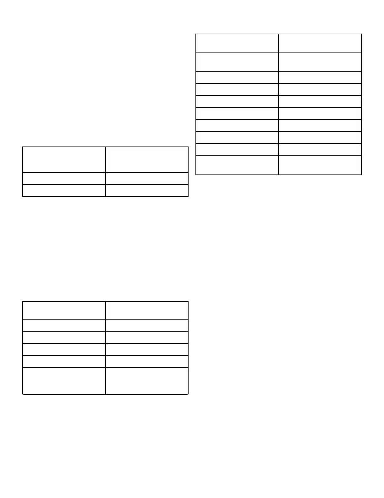
Each column of the table below contains a unique combination of
the words YES and NO that indicates if that column’s connection
is present.
Configuration Value
Comm Board "B" Head-
er Present
0 NO
16 YES
Table 4
Machine Configuration #2 Display Test d 30
This option shows the machine configuration values. To start test,
control must be in the Manual Diagnostic Mode Menu.
To enter, press the START (enter) keypad. For configuration val-
ue #2, the display will show bX XX. XXX is a number corre-
sponding to the capacity size of the machine. Refer to Table 5 .
To exit the test, simultaneously press the SELECT (∧) and DIS-
PLAY (∨) keypads. The control will return to the Manual Diag-
nostic Mode Menu.
Configuration Value Description
0 Invalid
1 25 Pound Tumble Dryer
2 30 Pound Tumble Dryer
3 35 Pound Tumble Dryer
4 T30 Pound Stack Tumble Dry-
er and S30 Stacked Washer-
Extractor/Tumble Dryer
Table 5 continues...
Configuration Value Description
5 T45 Pound Stack Tumble Dry-
er
6 50 Pound Tumble Dryer
7 55 Pound Tumble Dryer
9 75 Pound Tumble Dryer
10 F75 Pound Tumble Dryer
14 120 Pound Tumble Dryer
15 170 Pound Tumble Dryer
16 200 Pound Tumble Dryer
17 S50 Stacked Washer-Extrac-
tor/Tumble Dryer
Table 5
Machine Configuration #3 Display Test d 31
This option is not used on this model. 0 is always displayed.
Machine Configuration #4 Display Test d 32
This option shows the user which dipswitches are set on the con-
trol. To start test, control must be in the Manual Diagnostic Mode
Menu.
To Enter, press the START (enter) keypad. The display will show
dX XX with X XX representing a configuration value as shown
in Table 6 .
If supply voltage is 100-127 Volt per phase, the voltage configu-
ration should be 120 Volt.
If supply voltage is 200-240 Volt per phase, the voltage configu-
ration should be 240 Volt.
To exit the test, simultaneously press the SELECT (∧) and DIS-
PLAY (∨) keypads. The control will return to the Manual Diag-
nostic Mode Menu.
Each column in the table below contains a unique combination of
the words ON and OFF that indicates if that column’s dipswitch
is set on or off when the value is displayed.
Machine Diagnostic Functions
©
Copyright, Alliance Laundry Systems LLC -
DO NOT COPY or TRANSMIT
36 Part No. 70579901ENR9