Installation
32
©
Copyright, Alliance Laundry Systems LLC - DO NOT COPY or TRANSMIT Part No. 70458101ENR7
NOTE: Replacement outlet hoses are available (at
extra cost). Order 44073302 Hose, 21 in. (53 cm )21 in.
for 120 series and 44073303, 31 in. (79 cm) for 170 and
200 series.
Electrical Requirements
WARNING
Electrical power must be provided to tumbler at
all times. The fire suppression system will be
inoperative if the main electrical power supply is
disconnected.
W690
No independent external power source or supply connection is
necessary. Power to operate the 24 Volt fire suppression system
is from the rear junction/contactor box.
Auxiliary Alarm
The fire suppression system provides an auxiliary output signal
when the system is activated. During tumble dryer installation,
you have the option to connect a separate alarm system to this
auxiliary output. Potential uses of the auxiliary output include,
but are not limited to: (1) sounds an alarm, (2) activates a
building sprinkler system, (3) notifies a fire department, etc. Use
of the auxiliary output is not required for the fire suppression
system to operate, but may be used for additional protection.
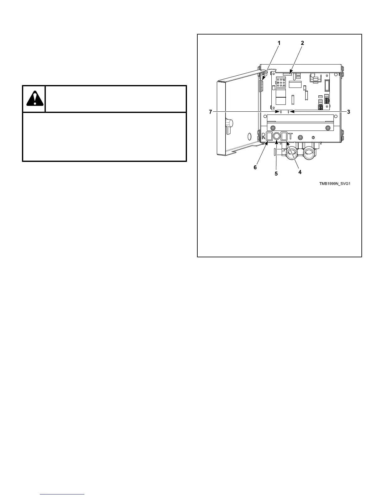
The connection to the auxiliary output is made through the FS-1
and FS-2 fast-on connections inside the fire suppression control
box. Refer to Figure 5 . The relay is rated for 24 VAC, 5.2 Amp,
sealed current.
NOTE: The auxiliary output is activated during fire
suppression system maintenance test sequence.
Consider this fact prior to your system test every three
months. (Example: If the external system uses the
auxiliary output to call the fire department, inform the
fire department before and after the fire suppression
system maintenance test.)
1
Opening for Auxiliary Alarm Cable
2
Fuse
3
Auxiliary Alarm Fast-On Connection
4
Test Button
5
Light
6
Reset Button
7
Auxiliary Alarm Fast-On Connection
Figure 5
Before Placing Tumble Dryer into
Service
1. Remove or open all panels and check accessible bolts, nuts,
screws, terminals and fittings for tightness.
2. Check belt tension and adjust if necessary. Refer to
Adjustments section.
3. Replace all panels and guards.
4. Turn on electrical supply to tumble dryer.
5. Open the supply valve for gas or steam heated tumble
dryers.
6. After performing the previous checks, start the tumble dryer
by pressing START. (Refer to the Operating section for
detailed instructions.) Release the start button and open the
loading door. The cylinder should stop rotating within seven
seconds after the door is opened a maximum of 2 inches
(51 mm) . If it does not, adjust the loading door switch.
Refer to Adjustments section.
7. Gas Tumble Dryers: Start the tumble dryer and check the
burner flame. Adjust the air inlet shutter as required. Refer
to Adjustments section.
 Loading...