96 801683
Section 5 Service Procedures
© Copyright, Alliance Laundry Systems LLC – DO NOT COPY or TRANSMIT
To reduce the risk of electric shock, fire, explosion, serious injury or death:
• Disconnect electric power to the washer before servicing.
• Never start the washer with any guards/panels removed.
• Whenever ground wires are removed during servicing, these ground wires must be
reconnected to ensure that the washer is properly grounded.
• Motor not grounded! Disconnect electric power before servicing motor.
W485
WARNING
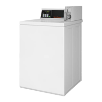
40. CARD READER
Front Control Washers
a. Removal:
(1) Unlock control panel. Refer to Figure 14,
Step 1.
(2) Pull top of control panel away from control
cabinet far enough to allow lifting control
panel up and off the rail support of the
control cabinet front. Refer to Figure 14,
Step 2.
(3) Remove control panel away from control
cabinet as far as wires permit. Refer to
Figure 14, Step 3.
(4) Remove two screws holding front of
cabinet top to top front edge of control
cabinet front. Refer to Figure 22.
(5) If area or space permits, lift cabinet top to a
vertical position by hinging it on the rear
hinges.
NOTE: To avoid damage to hinges, be sure to
support cabinet top with a small chain or something
similar. Refer to Figure 23.
(6) Disconnect card reader harness at
disconnect block.
(7) Use a 3/8 inch square drive socket, with
number 310P4 1/4 inch Ratchet Extension
Tool, to remove screws or nuts holding card
reader to control cabinet front and carefully
remove card reader out through top of
control cabinet. Refer to Figure 39.
NOTE: A 3/8 inch square drive socket, size 7/16
inch, fits over end of the 310P4 Extension Tool. A
1/4 inch ratchet fits in the other end. Refer to
Figure 39.
b. Installation:
(1) Carefully place card reader into opening in
control cabinet front.
(2) Using a 3/8 inch square drive 7/16 inch
socket with number 310P4 1/4 inch Ratchet
Extension Tool, secure card reader to
control cabinet front with screws or nuts
previously removed. Refer to Figure 39.
Then tighten screws or nuts firmly.
(3) Reconnect card reader harness.
(4) Lower cabinet top into position and
reinstall two screws (previously removed)
holding cabinet top to top front edge of
control cabinet front. Refer to Figure 22.
(5) Reinstall control panel in control cabinet
and lock control panel.
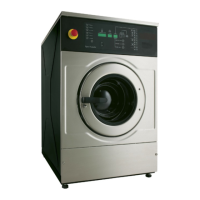
Rear Control Washers
a. Remove two control panel attaching screws.
Refer to Figure 15. Lay control panel assembly
forward on protective pad on cabinet top.
b. Disconnect card reader harness.
c. Remove four nuts holding card reader bracket
to control panel. Refer to Figure 21.
d. Remove card reader assembly.
e. Disengage card reader.
 Loading...