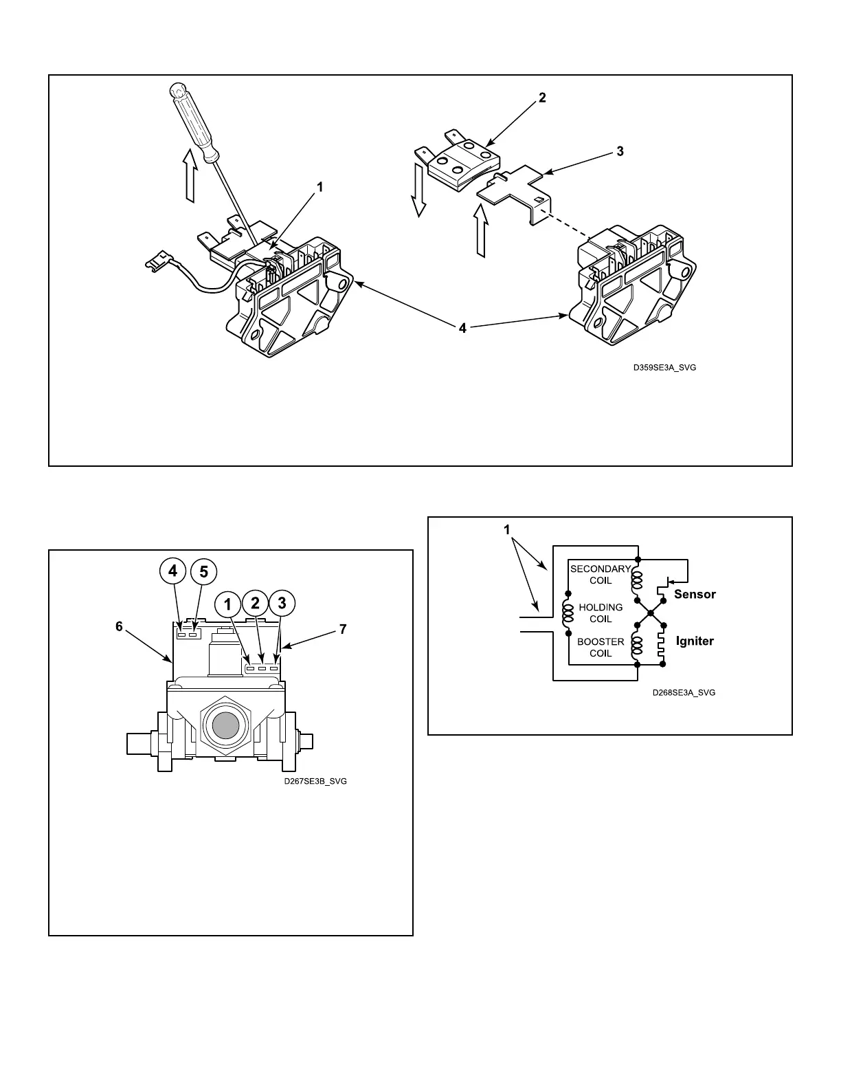
1. Top of Motor Switch
2. Thermal Overload Protector
3. Plastic Clip
4. Motor Switch
Figure 14
Burner System Operation - Gas Models
1. Terminal 1
2. Terminal 2
3. Terminal 3
4. Terminal 4
5. Terminal 5
6. Secondary Coil
7. Holding Coil and Booster Coil (Split Coil Valve)
Figure 15
1. 120 Volt, 60 Hertz Electrical Supply Line
Figure 16
Gas Models - Refer to Figure 15 and Figure 16 .
1. Components. This burner has four basic components: a sili-
con carbide (glow bar) igniter, burner tube, sensor, and a two-
stage gas valve consisting of a split-coil valve and a secon-
dary coil valve. The split-coil valve is opened when the dryer
thermostat calls for heat, while the secondary valve does not
open until the igniter has attained ignition temperature.
2. Pre-Ignition Circuits. When the dryer thermostat calls for
heat, circuits are completed through the holding coil, sensor,
booster coil and igniter. Both coils must be energized to open
the split-coil valve. Once opened, the holding coil can hold
the valve open without assistance from the booster coil. The
sensor triggers the current to travel around the secondary coil
and through the igniter, causing the igniter to get hot.
Test Procedures
©
Copyright, Alliance Laundry Systems LLC -
DO NOT COPY or TRANSMIT
59 Part No. D515519R3
 Loading...