1. While supporting the access panel, remove two screws from
bottom edge of access panel.
2. Gently lower the access panel to disengage locators from bot-
tom edge of front panel.
3. Close main gas shut-off valve. Refer to Figure 22 and Figure
23 .
4. Remove valve wire harness disconnect block from the hold-
ing and booster coil. Refer to Figure 17 and Figure 18 .
5. Plug dryer power cord into wall receptacle, and start the dryer
in a heat setting (refer to dryer Operating Instructions).
6. Set test meter to read AC voltage and apply meter probes into
terminals on the dryer harness plug that would correspond to
terminals “1” and “2” on the coil. Refer to Figure 15 and Fig-
ure 16 . Meter should register line voltage in all temperature
settings, except NO HEAT which should read “zero” VAC.
7. If meter does not read line voltage in step “f”, check motor
switch, thermostats, fabric switch, or control.
WARNING
To reduce the risk of fire, explosion and electric
shock, close the valve in the gas supply line to the
gas dryer and disconnect the electrical power unless
gas or power supplies are required to perform test
procedure.
W263
Gas Valve Coils Check (Gas Models)
1. While supporting the access panel, remove two screws from
bottom edge of access panel.
2. Gently lower the access panel to disengage locators from bot-
tom edge of front panel.
3. Close main gas shut-off valve. Refer to Figure 22 and Figure
23 .
4. Remove disconnect blocks from gas valve coils.
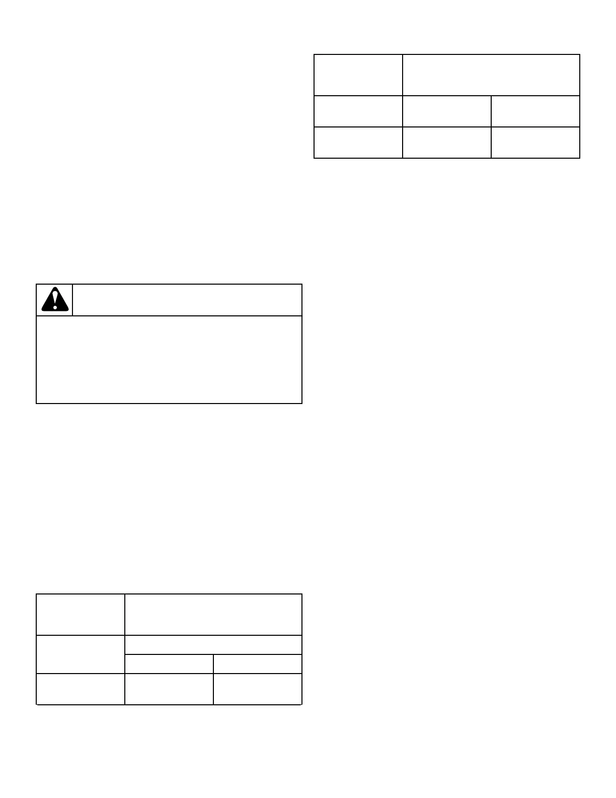
5. Set test meter to read Ohms and put meter probes to terminals
shown in Figure 17 , Figure 18 , Figure 19 , and in the fol-
lowing chart.
Silicon Carbide Ignition:
Coil Tolerance
Readings
Meter probes to ter-
minals:
Meter should read:
50 Hertz 60 Hertz
Holding Coil – Ter-
minals 1 & 2
1700 ± 285 Ohms 1365 ± 230 Ohms
Table 2 continues...
Coil Tolerance
Readings
Booster Coil – Ter-
minals 1 & 3
685 ± 115 Ohms 560 ± 100 Ohms
Secondary Coil –
Terminals 4 & 5
1680 ± 285 Ohms 1325 ± 230 Ohm
Table 2
Silicon Nitride Ignition: Both coils should read between
2400-2800 Ohms.
NOTE: If meter registers any other readings than those
listed above, the respective coil(s) should be replaced.
Sensor Check (Gas Models)
1. While supporting the access panel, remove two screws from
bottom edge of access panel.
2. Gently lower the access panel to disengage locators from bot-
tom edge of front panel.
3. Close main gas shut-off valve. Refer to Figure 22 and Figure
23 .
4. Remove wires from sensor terminals.
5. Set test meter to read Ohms and put meter probes on sensor
terminals. Meter should read “zero” Ohms. If meter registers
an Ohm reading of any amount, replace sensor.
Igniter Check - Gas Models
1. While supporting the access panel, remove two screws from
bottom edge of access panel.
2. Gently lower the access panel to disengage locators from bot-
tom edge of front panel.
3. Close main gas shut-off valve. Refer to Figure 22 and Figure
23 .
4. Disconnect igniter wires at disconnect block.
5. Set test meter to read Ohms and put meter probes on terminals
of igniter wires.
6. Silicon Carbide Igniter: Meter should read between 45 –
200 Ohms. Silicon Nitride Igniter: Meter should read be-
tween 49 – 88 Ohms.
NOTE: If meter does not read appropriate Ohms, then
replace the igniter.
IMPORTANT: Always examine all wires, terminals and
connectors to be sure wiring is correct before replac-
ing any components.
Ignition Control Grounding Check -
Silicon Nitride Ignition
Test Procedures
©
Copyright, Alliance Laundry Systems LLC -
DO NOT COPY or TRANSMIT
61 Part No. D515519R3
 Loading...