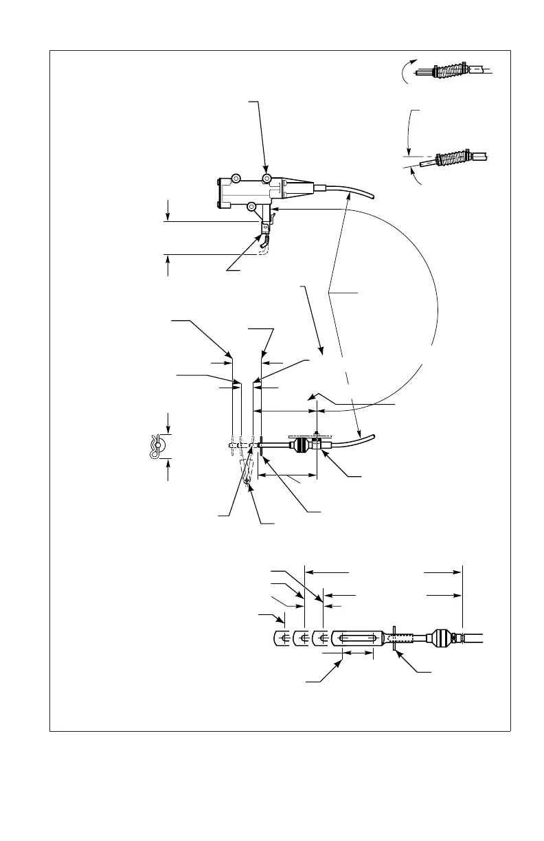
Fuel lever attachment linkage or bracket must
allow fuel lever to return to closed throttle position
when sensor rod is maintained at full throttle position.
Attach the throttle sensor directly to the engine fuel
lever with no breakover or yield linkages between the
engine fuel lever shaft and the attachment point of the
throttle sensor.
MOUNTING PROVISION:
Use M6 x 1.00 or
1
⁄4-20 in. series bolts 3 places
Torque M6 x 1.00 bolt to 10–13 N•m (84–120 lb in.)
Torque
1
⁄4-20 in. series bolts to 13–14 N•m (108–132 lb in.)
Mount to a solid frame member. Flatness of
chassis mounting surface must not exceed
0.8 mm (0.03 in.).
R 152.0 mm (6.00 in.) MIN
ALLOWANCE RADIUS
FULLY
RETRACTED
FULL THROTTLE
118.1 mm (4.65 in.)
30.2 mm (1.19 in.)
55.0 mm (2.17 in.)
MIN REQUIRED
FOR CONNECTION
REMOVAL
WIRING HARNESS
OPERATING BAND 15.2 – 22.9 mm
(0.6 – 0.9 in.)
47.5 mm (1.87 in.)
118.1 mm
(4.65 in.)
95.2 mm
(3.75 in.)
93.45 mm (3.679 in.)
87.15 mm (3.431 in.)
HITCH PIN CLIP
ENGINE FUEL LEVER
Attach to engine or governor
housing using clamp and shims as
required. Clamp must positively
lock in cable groove.
FULLY EXTENDED
FORCE REQUIRED
26.7 N (6.0 LB) MAX
Fuel control must not move
the throttle sensor beyond
the closed throttle position
at any time.
The location of the
clamping bracket relative
to the fuel lever at closed
throttle must be maintained
within this range.
(NOTE: Mounting length
+ 50.8 mm (2 inches) equals
cable length)
CLOSED THROTTLE
95.2 mm (3.75 in.)
MOUNTING
LENGTH
BENDING LOAD
APPLIED
UNACCEPTABLE INSTALLATION
Attachment must provide freedom
of motion to allow cable loading in
tension only (no bending loads).
ACCEPTABLE INSTALLATION
10.0
°
MAX INSTALLED
OPERATING ANGLE
IN ALL DIRECTIONS
LOADING IN
TENSION ONLY
V00430.06
HITCH PIN CLIP
38.1 mm (1.50 in.)
FULLY RETRACTED
FULLY EXTENDED
CLOSED THROTTLE
183.1 mm (7.21 in.) MAX
FULL THROTTLE
SAME AS WITHOUT
SLIP LINK
OPTIONAL THROTTLE SENSOR ASSEMBLY WITH SLIP LINK
160.2 mm (6.31 in.) MIN
Figure 5–6. Hitch-Pin Throttle Position Sensor Installation Diagram
67
 Loading...