Instructions FMA03 26.04.2013 Page 8/21
3.2 The connectors panel of the FMA03
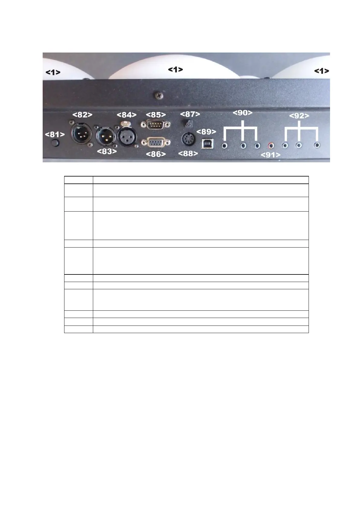
The connectors panel of the FMA03 is situated at the top of the backside
No.
Functional description
<81>
ON/OFF button
press shortly to start, hold pressed for 2sec. to shut off the FMA03
<82>
Power connector (DC 12V)
Please only use the original power supply (included in delivery)
<83>
<84>
RS485 interfaces* via XLR 3-pin male and female
Preset for communication with allstar peripheral devices (repetition lights and
running time for finales, slave scoring machines, podium lamps, etc.) Further
protocols can be selected individually.
<85>
RS232 interface* via sub-D 9-pin male
<86>
RS422 interface* via sub-D 9-pin female
* Transmission protocols and standards can be individually selected on these three interfaces.
For example for data exchange with large-format screens (KABCOM, Swiss Timing), video
refereeing and others.
<87> Connector for wired remote control
<88> Connector (analogue) for external repetition lights (7-pin diode socket)
<89>
USB socket
Firmware and other software (FIE regulation updates, new functions etc.) can
be easily updated via USB interface without chip changing
<90> Connector 3-pin: fencer green side
<91> Connector: piste
<92> Connector 3-pin: fencer red side