Setup and connection
5.3 Installing the motor
Only necessary if the pump unit is assembled on site.
5.3.1 Installing the motor on pumps in flange versions
NOTE
Material d amage caused by knocks and bumps!
Keep the coupling halves properly aligned when slipping
them on.
Do not knock or hit any components of the pump.
1. Smear a very thin coat of molybdenum disulfide (e.g.
Molykote) on the shaft ends of the pump and motor.
2. Insert the shaft keys.
3. Slip on the p ump-side and motor-side coupling halves in
line.
– Without a mounting fixture: Remove the rubber buffers
and heat the coupling halves up to approximately
100 °C.
4. Tighten the grub screws on both coupling h alves.
5. Lift the motor and position it on the pump bracket.
6. Check the distance between the coupling halves with a
feeler gauge:
– Permissible gap (→ 9.2.4 Coupling assembly,
Page 32).
– Use the feeler gauge to measure the gap (A) between
the coupling halves.
– Align the coupling halves if the gap is too wide.
7. Tighten the motor bolts.
5.4 Planning the pipes
5.4.1 Specifying supports and flange connections
NOTE
Material damage due to excessive forces and torques
exerted by the piping on the pump!
Do not exceed the p ermissible values (→ flange loads
according to EN ISO 14847)
1. Calculate the pipe forces, taking every possible operating
condition into account:
–Cold/warm
– Empty/full
– Depressurized/pressurized
– Positional changes of the fl anges
2. Ensure the pipe supports have p ermanent low-friction
properties and do not seize up due to corrosion.
5.4.2 Specifying nominal diameters
Keep the flow resistance in the pipes as low as possible.
1. Make sure the nominal suction pipe d iameter is ≥ the nom-
inal suction branch diameter.
– Makesuretheflow rate is be low 1 m/s
2. Make sure the nominal pressure pipe diameter is ≥ the
nominal outlet flange diameter.
– Makesuretheflow rate is be low 3 m/s
5.4.3 Specifying pipe lengths
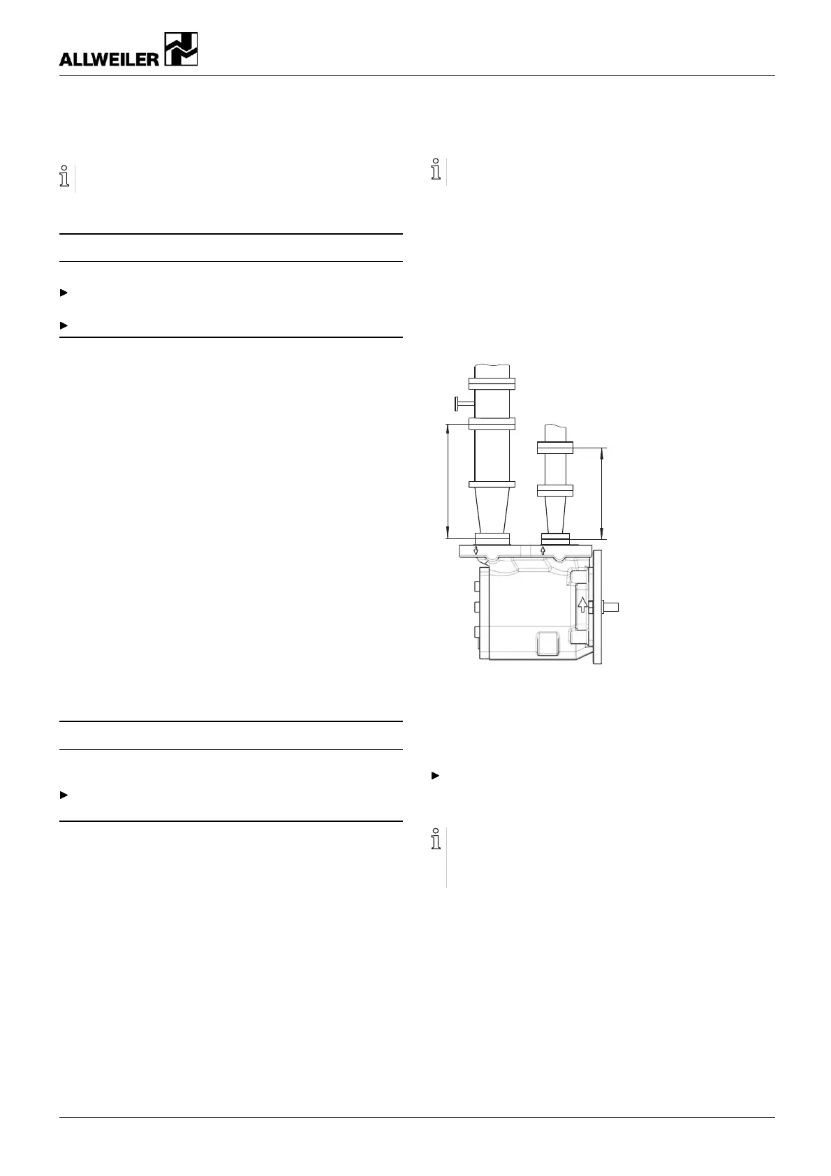
B
A
Fig. 7 Stra ight pipe lengths upstream and downstream
of the pump (recommended)
A > 5 x nominal suction pipe diameter
B > 5 x nominal pressure pipe diameter
Recommendation: Provide long, straight pipes upstream
and downstream of the p ump .
– This will improve the suction performance of the pump.
Suction side: Shorter pipes are possible but may restrict
the hydraulic performance.
Pressure side: Shorter pipes are possible but can result in
increased operating noise.
5.4.4 Optimizingchanges in cross-section and direction
1. Avoid bending radii of less than 1.5 times the nominal pipe
diameter.
2. Avoid abrupt cha nges of cross-section and direction along
the pip ing.
626.0005 GB – 550 041 BA-2014.01 SPF s eries 15



 To Next Page