Layout and function
3 Layout and function
3.1 Label
3.1.1 Type p late
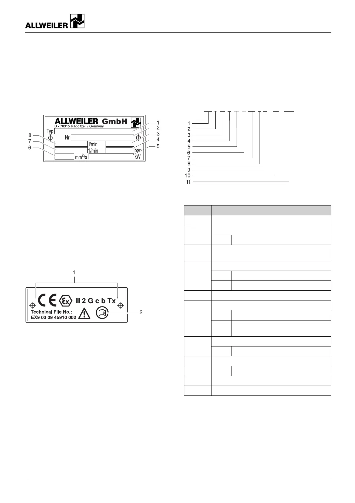
Fig. 1 Type plate (example)
1Pumptype
2 Pump number
3 Year of manufacture
4 Pumping pressure
5 Power consumption
6 Kinematic viscosity
7 Motor speed
8Flowrate
3.1.2 ATEX plate
Fig. 2 ATEX plate (example)
1 Explosion protection mark
2 Referen ce to ATEX additional instr
uctions
3.1.3 Pump type code
SP F 10 R 46 G 8.3 F E - ... - W20
Fig. 3 Pump t ype code (example)
Position Meaning
1
Series (SP)
Design2
F Flange pump
3
Size (theoretical flow rate in l/min at normal
inclination and 1450 rpm)
Spindle pitch direction
R
Right (standard)
4
L
Left
5
Spindle p itch angle in degrees
Design characteristic
G
Internal sleeve bearing
6
U
Internal antifriction be aring, uncooled,
unheated
Shaft seal
7
8.3 Mechanical seal
8 Filter version
9E
Versionwithelectricfilter heating
10
Pressure relief valve adjustment ran ge
11 Material key
Tab. 5 Pump t ype code
626.0005 GB – 550 041 BA-2014.01 SPF s eries 9