EasyManua.ls Logo

Alpha ESS SMILE5 - Page 28

Alpha ESS SMILE5
113 pages
Print Icon
To Next Page IconTo Next Page
To Previous Page IconTo Previous Page
Loading...
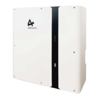
Product Introduction and Application Scenarios
26
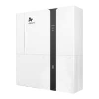
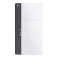
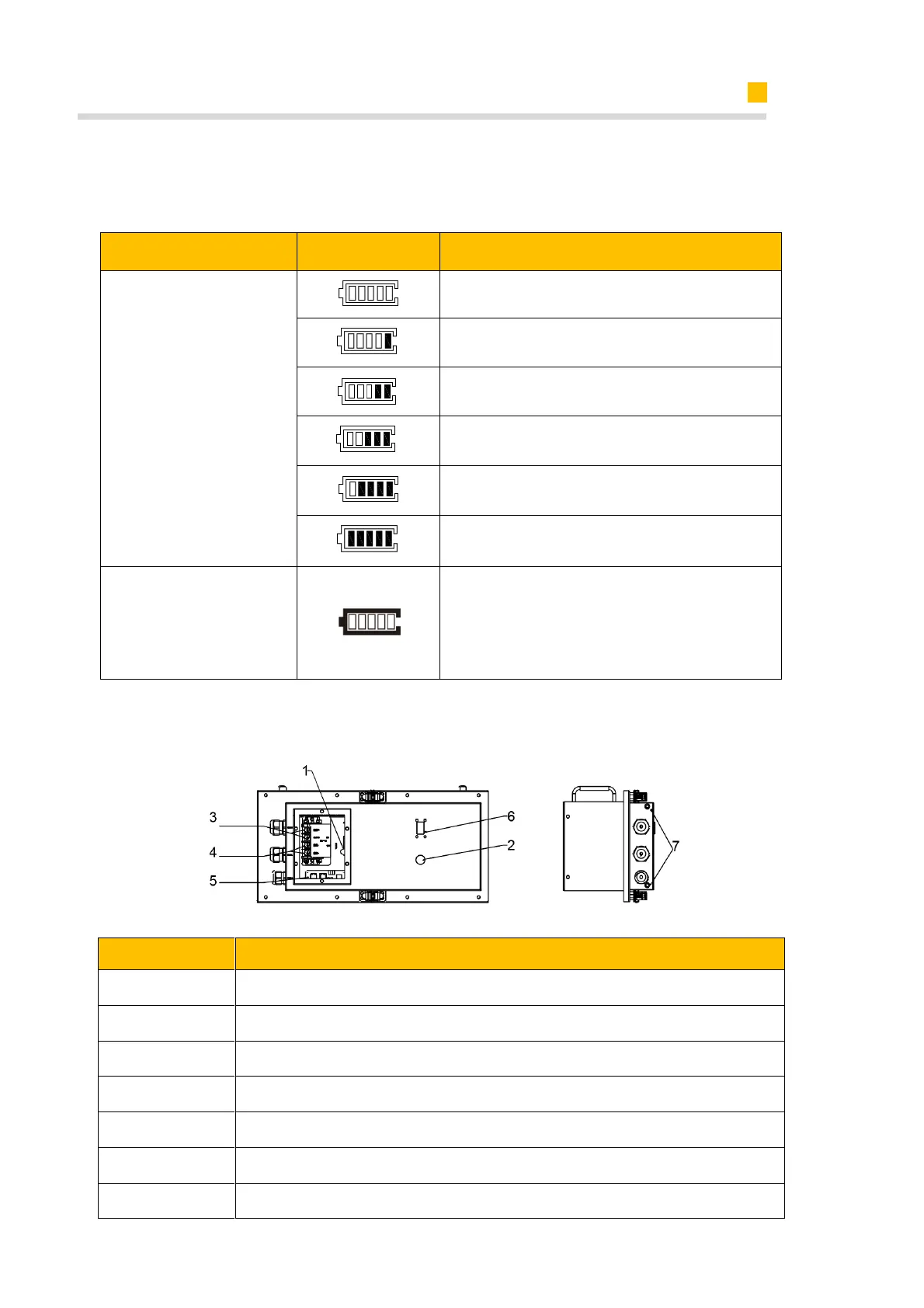
Different colors of inner grids of the battery LED display represent different states
green for SOC state, red for error state.
The LED indicators provide information about the SOC operational status of the battery
pack.
Item
SOC Status
Description
SOC Description
SOC<5%
5%≤SOC<25%
25%≤SOC<50%
50%≤SOC<75%
75%≤SOC<95%
SOC≥95%
LED Outer Ring Light
Flicker Status
Work: green light flicker every 10s;
Standby: green light flicker every 1s;
Protection: green light flicker every 3s;
Error: red light flicker every 3s;
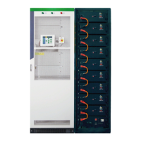
Connection area overview of M4856-P
Position
Designation
1
Battery Breaker
2
Battery Power Button
3
Battery+ Power Connector
4
Battery- Power Connector
5
BMS COM Ports
6
Battery LED Display
7
Grounding

Table of Contents

Other manuals for Alpha ESS SMILE5

Related product manuals