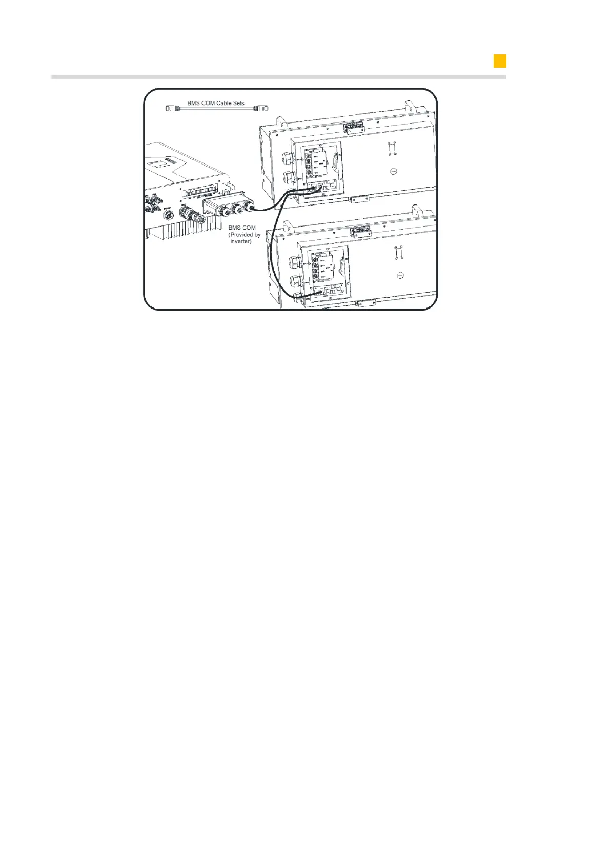
6.6.3. AUX/LAN/PV-CT/DRM、RRCR/GRID-CT、Meter/RS485/BMS Connection
For other communication (AUX, LAN, RRCR, DRM, Meter, CAN/RS485) connection,
please follow the below steps.
1. Loosen the cable glands on the COM connection cover, and then unscrew the 4
screws on the COM connection cover.
2. Lead the communication cables through the cable glands of the COM connection
cover, don’t tighten the swivel nuts of the cable glands.
Insert the RJ45 plugs to the relative RJ45 sockets.
1) For meter wiring, refer to Chapter 6.4.2 and 6.4.3 for Chint or Acrel Meter Connec-
tion.
2) If DRM support is specified, the system may only be used in conjunction with a
Demand Response Enabling Device (DRED). This ensures that the system imple-
ments the commands from the grid operator for active power limitation at all times.
The system and the Demand Response Enabling Device (DRED) must be connected
in the same network.
Only DRM0 is available for SMILE5-INV.
3) Take out 6 pin terminal block for AUX connection. To do wiring connection, insert a
screwdriver (blade width: 1.2 mm) into the relative connection position side.
For AUX position definition, please see the AUX wiring documentation.
3. Place the COM connection cover against the inverter housing and tighten the 4
screws, at last secure the swivel nut of the cable glands.
The pin definition of the communication ports: