63
L1
-X8
L2 L3 PE
1
2
-K1
/2.3
3
4
R S T
U V W
-N1
M
3
T1
T2
T3
PE
-M1
VD1
5
6
11
12
-K1
/2.3
ϑ
-E4
-R20
1
2
-K2
/2.4
3
4
R S T
U V W
-N2
M
3
T1
T2
T3
PE
-M2
VD2
5
6
11
12
-K2
/2.4
ϑ
-E5 -R21
-F4
1
2
-K3
/2.5
-F5
3
4
5
6
-F6
1
2
-K5
/2.7
3
4
M
3
PE
1U
1V
1W
2W
2U
2V
-M3
VENT1
5
6
1
2
-K4
/2.6
3
4
5
6
TK
TK
-R23
L Reg
/2.1
N Reg
/2.1
MOT
/2.1
R23
/2.1
PE
/2.1
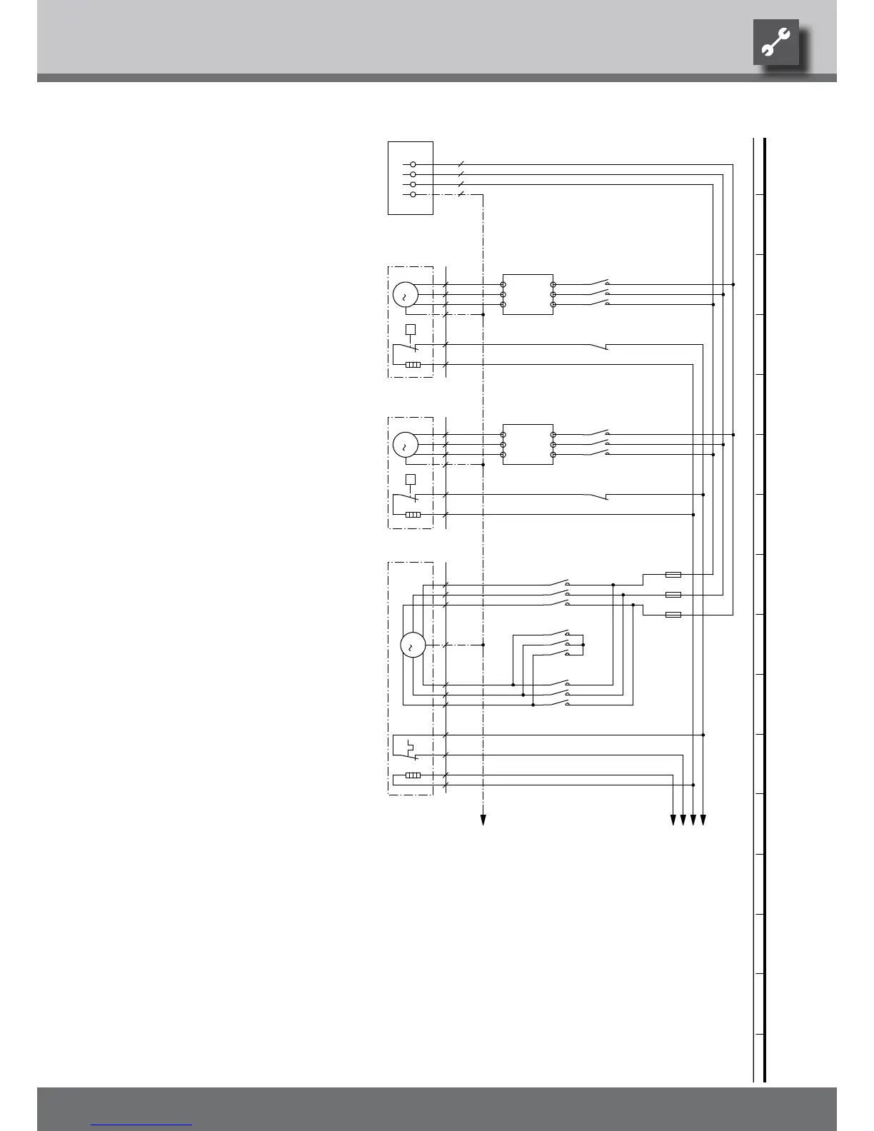
E4
Thermostat Sump heating for compressor 1
Motor protection fan
M1
N1
4 8
Triangle contactor fan
F3
Fan
K4
VD1
3~PE/400V/50Hz
K1
Distribution box power supply output compressor
Contactor for compressor 1
PE
UK817339
VD1
5
-M3
3~PE/400V/50Hz
13
Operating materials
3
-M1
K3
VENT1
-F3
Legend:
Power supply compressor; right-hand rot. field is mandatory!
1 10
Star contactor fan
4
Network protection fan
2PE2
1
X8
75
2
VD2
Sump heating for compressor 2
VD2
Compressor 1
K5
-M2
Fuses ventilatorF4 - F6
E5
Thermostat Sump heating for compressor 2
9
K2
gn/ge3
Starting current limit compressor 2
Sump heating for compressor 1R20
M2
1
M3
Contactor for compressor 2
Starting current limit compressor 1
Function
2
R23
5
6
R21
Compressor 2
PE
N2
Nozzle heating fan
3
4
We reserve the right to modify technical specifications without prior notice.
UK830532/200610 © Alpha-InnoTec GmbH
Circuit diagram 1/2 LW 310A