20
Subject to change without notice | 83057000jUK – Translation of the original operating manual | ait-deutschland GmbH
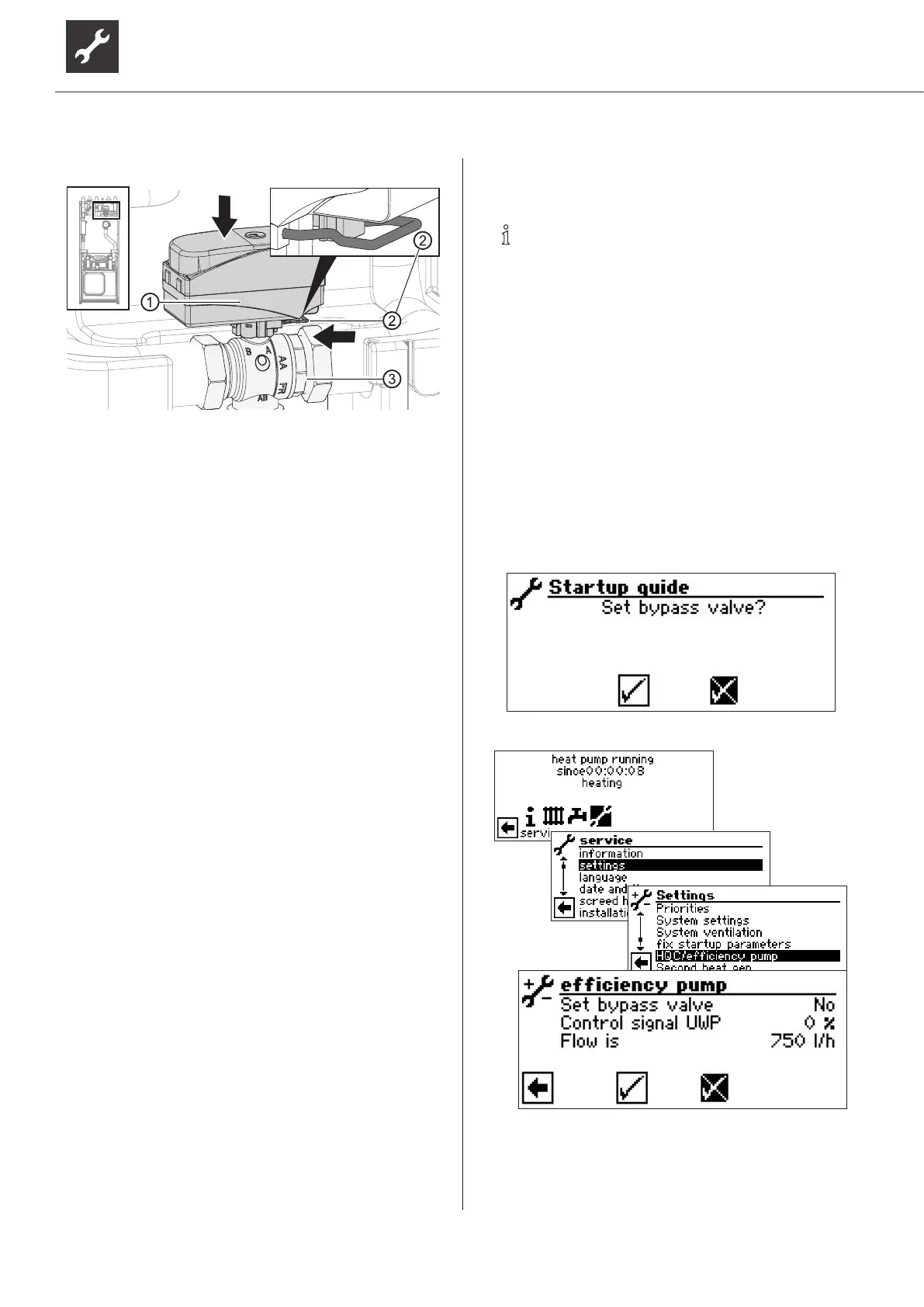
8. Insert the U-clip (②)
9. Ensure that the U-clip has latched into position
correctly:
Valve motor sits securely on the 3-way changeo-
ver valve.
Both prongs of the U-clip sit on the lug.
The tips of the U-clip are visible by approx. 2 mm
!).
10. Screw the front panel of the module box.
8 Insulate hydraulic connections
1. Insulate heating circuit and heat source according
to the local regulations.
2.
3.
4. Insulate the internal piping of the module box with
included.
5. Insulate external piping on site.
6.
7.
tight.
8. Insulate the heating circuit of units with cooling
9.
higher, insulate the venting valve at the cold heat
exchanger too so that it is vapour-tight. To do this,
glue the insulation strips on top of each other
(
9
NOTE
The activities in this section are only nec-
the maximum return temperature can be
exceeded and the heat pump switches to
high-pressure fault.
valve to the right to increase the tempera-
it to the left to reduce it.
System is running in heating mode (ideally in cold
condition).
The IBN assistant already provides the option, in the
-
lic system.

 Loading...


