40
Subject to change without notice | 83057000jUK – Translation of the original operating manual | ait-deutschland GmbH
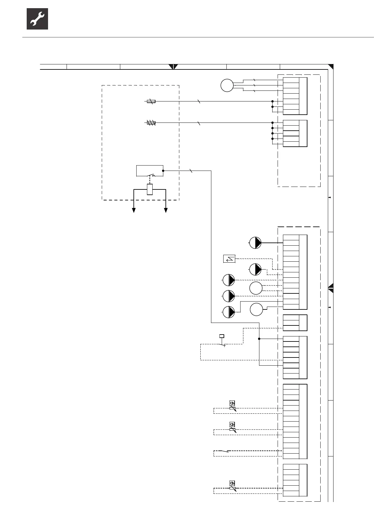
Information on fuses can be found in the technical data
HUP/ZUP
-X10
-F11 -F13
-X8
EVU
Legend:
Equipement
A1
A2
A3
EVU
F11
F13
Terminals
OUT9
OUT10
OUT11
OUT12
OUT13
OUT14
OUT15
OUT16
OUT17
IN4
IN5
IN6
NTC8
NTC10
NTC12
NTC15
X3-X12
X8
X9
VBO
ZW2/SST
acronym
ZW2/SST
ZIP
FP1
MZ1/MIS
MA1/MIS
ZUP
HUP
BUP
ASD
EVU1
EVU2
TRL ext.
TA
TB1
TBW
X3-X12
X8
X9
-X3
ZIP
FP1
MIS
UK
Function
Controller board; Attention: I-max = 6,3A/230VAC
Terminals in heat pump switchbox
Sub-distribution unit internal installation
Energy supplier contact; closed on release; bridge if no blocking interval
Cut out controller unit
Cut out compressor / auxiliary heating
Brine circulation pump
230V Cooling signal (active when cooling enabled)
Control signal of additional heat generator 2 (alternative is general malfunction)
circulation pump
Pump for mixing circuit 1
Charge/discharge/cooling mixer 1 closed
Charge/discharge/cooling mixer 1 open
Auxiliary circulation pump
Heating circuit circulating pump
Diverting valve for domestic hot water
Brine pressure pressostat; provided by cust. if necessary
Energy supplier contact; closed on release; bridge if no blocking interval Energy
supplier contact; closed on release; bridge if no blocking interval External return
sensor
External sensor
Dewpoint monitor bridge; cooling interrupted if contact open / Sensor MK1
Accessories: Process water sensor/thermostat
Terminal strips on controller board
Power supply compressor; right-hand rot. field is mandatory!
Power supply, output, additional heating
Terminal in switch box heat pump
ZUP
831200c
BUP
HUP
-X4
ASD
-X5 -X8 -X9
1 2 3 4 5 6 7 8
A
B
C
D
E
F
A
B
C
D
E
F
Blatt
Bl.
1
1
3 4 5 6 7
AIT
831200c
Klemmenplan
ait-deutschland GmbH
PEP010/2015
ÄM021/2016
10.03.2015
20.10.2015
30.06.2016
AP
AP
AP
1
2
3
4
L
1~N/PE/230V/50Hz
3
N
PE
PE
3~N/PE/400V/50Hz
5
N
L1
L2
L3
2
A1A2
OUT4
OUT5
OUT6
OUT7
OUT8
OUT9
OUT10
OUT11
OUT12
OUT13
OUT14
OUT15
OUT16
OUT17
L
L
L
L
IN1
P
IN2
IN3
IN4
IN5
IN6
IN7
NTC6
M6
NTC7
M7
NTC8
TRL ext.
M8
NTC9
M9
NTC10
TA
M10
NTC11
TPF
M11
NTC12
TB1
M12
NTC13
M13
NTC14
M14
NTC15
TBW
M15
A2
A3
A1
Änderung Datum
Datum
Bearbeiter
Geprüft
NormName
10.03.2015
Pfleger
R.
bl br bk
M
M
M
OUT5 VBO
Terminal diagram SWCV 62(H)(K)3 – SWCV 92(H)(K)3

 Loading...


