12
We reserve the right to make technical changes.
UK830509/200114 © Alpha-InnoTec GmbH
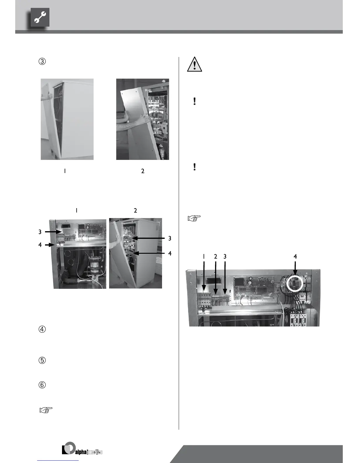
Take the front panel off its hinges and put in a safe
place…
1 Size 1
2 Size 2
Gain an overview of the inside of the device…
1 Size 1
2 Size 2
3 Electrical switch cabinet
4 Device intermediate bottom
Open the electrical switch cabinets of the device…
For this only loosen the upper two screws of the
covering plate. Remove the remaining screws. The
covering plate can then be taken off its hinges…
Route load and external control and sensor lines to
the terminals via the cable duct. Tighten strain relief
screws…
Make electrical connections according to the di-
mensional data of the terminal diagram and circuit
diagrams…
"Terminal Diagram" and "Circuit Diagrams".
DANGER!
Only carry out electrical work according
to the terminal diagram and circuit dia-
grams applicable for the device type.
CAUTION.
Ensure clockwise rotational eld of the
load infeed (compressor).
– Operation with the wrong rotational
direction of the compressor can result
in serious, irreparable damage to the
compressor.
CAUTION.
Always provide the power supply for the
heat pump with a 3-pole automatic circuit
breaker with at least 3mm contact dis-
tance.
Note the size of the tripping current.
Overview "Technical Data/Scope of Supply", sec-
tion "Electrics".
Size 1:
1 Connection for power
compressor 3~PE
2 Connection for control
3 N/PE
4 Phase sequence relay
 Loading...


