13
We reserve the right to make technical changes.
UK830509/200114 © Alpha-InnoTec GmbH
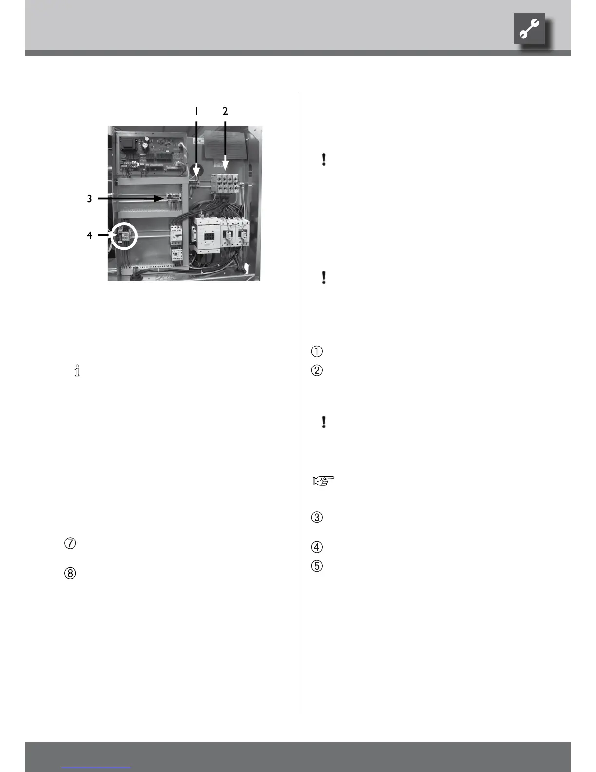
Size 2:
1 Connection for control
2 Connection for power
compressor 3~PE
3 N/PE
4 Phase sequence relay
NOTE.
The control element of the heat and heat
pump regulator can be a connection with
a computer or network using an network
cable designed for such pruposes, thus
allowing the heating and heat pump
regulator to be controlled remotely.
If such a connection is desired, install a
screened network cable (category 6, with
RJ-45 plug) through the unit when installing
the connections and run it through the
front facade of the unit, parallel to the
already-present heating and heat pump
regulator control cable.
Close the switch cabinet inside the device after n-
ishing all the electrical work…
Close the front panel of the device if no further in-
stallation work is to be carried out directly after-
wards.
Rinsing, Filling and Ventilating
the System
CAUTION.
The system must be absolutely free from
air before commissioning.
Rinsing, filling and bleeding the heat souRCe
Dirt and deposits in the heat source can lead to malfunc-
tions.
CAUTION.
The drainage pipe must be connected to
the safety assembly before rinsing and ll-
ing the heat source.
Proceed as follows:
Rinse heat source system thoroughly…
Thoroughly mix the antifreeze available as an acces-
sory with water in the required ratio. Only ll the
heat source after mixing…
CAUTION.
The concentration of the antifreeze in the
water must have the value indicated for
your device type.
Overview “Technical Data/Scope of Supply”, sec-
tion “Heat Source”.
Check the concentration of the antifreeze in the
mixture…
Fill the heat source with antifreeze mixture…
Bleed the heat source.
 Loading...


