17
We reserve the right to make technical changes.
UK830509/200114 © Alpha-InnoTec GmbH
Buffer tank
Hydraulic integration of the heat pump requires a buffer
tank in the heating circuit. The volume required for the
buffer tank can be derived from the following formula:
V
Buffer tank
=
Min. throughput of heating circuit volumetric ow /
hour
10
For the minimum throughput of the heating cir-
cuit volumetric ow, see the overview “Techni-
cal Data/scope of Supply”, section “Heating Cir-
cuit”.
Circulation Pumps
CAUTION.
Always note the model.
Do not use regulated circulating pumps.
Circulating pumps and domestic hot wa-
ter circulation pumps must be multi-stage,
regulated pumps.
NOTE:
The minimum hot water, heat source vol-
umetric ow must be ensured!
NOTE:
The viscosity of the brine must be ob-
served when dimensioning the heat source
circulating pump!
NOTE:
A motor protection switch for the heat
source circulating pump is integrated in
the heat pump!
Setting range “Technical Data/Scope of Supply”
Electrics
For the minimum volumetric ow rate of the
heat circuit/heat source, see overview “Tech-
nical Data/Scope of Supply” section “Heat Cir-
cuit” “Heat Source” for the relevant type.
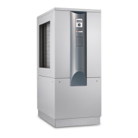
Beginning rst on one side and moving upwards,
lock the screen’s snap-in lugs in place in the slots
provided on the front of the facade…
Next, on the opposite side, moving upwards.
Lock the screen’s snap-in lugs in place in the slots
provided on the front of the facade…
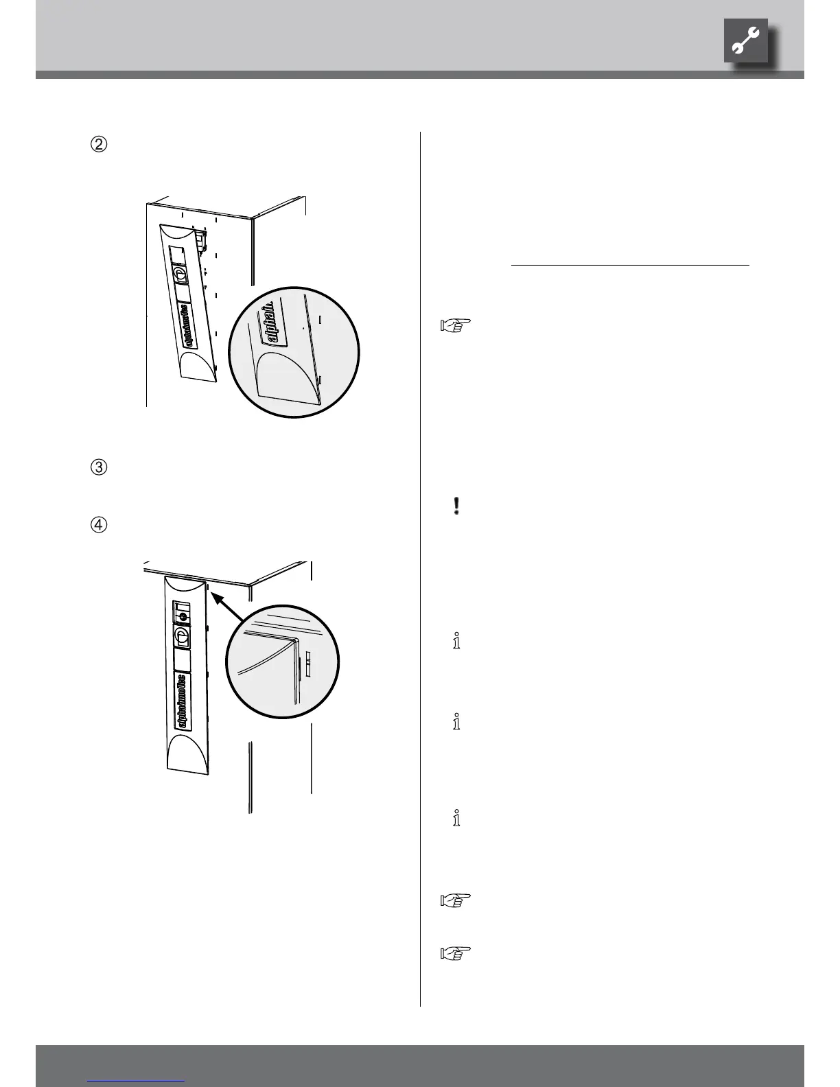
Finally, press the screen’s upper snap-in lugs into
the slots provided on the front of the facade.
Removing the sCReen
In order to remove the screen, the snap-in lugs must
rst be loosened by pressing one side completely
toward the middle of the screen. Thereafter, remove
the snap-in lugs from the opposite side.
 Loading...


