50
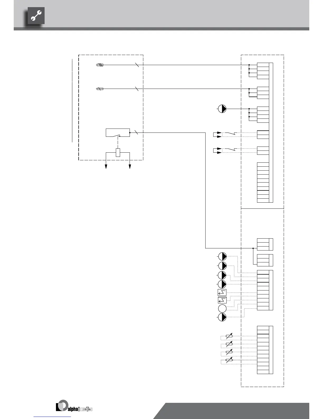
-F10 -F12
A1
A2
M
N
ZIP
BOSUP
-X2
RFV
-X3
MIS
TA
External flow rate switch; bridge if no switch can be connected
N
BOSUP
DFS
N
BUP
8
MOT
X7:9,10
Energy supplier contact; closed on release; bridge if no blocking interval
7
MA1
A3
RFV
HUP
PE
Sensor mixing circuit 1
N
PE
TB1
N
2
GND
GND
X7:L,N,PE
ZUP
1~N/PE/230V/50Hz
MZ1
Power supply, controller 230V
Well / brine pump
PE
PE
HUP
PE
PE
-X7
TB1
Well / brine pump
No function
L2
Auxiliary circulation pump
TA
L1
3-pol. Cut out compressor; Attention: Right-hand rot. field is mandatory!
Control signal of additional heat generator 2 (alternative is general malfunction)
External sensor
F12
A1
F10
ZW2/SST
PE
HUP
Name
L1
A2
L1
A3
VBO
A1
Cut out controller unit
ZUP
4
ZW2/SST
Terminal strip in switchbox of heat pump; N/PE distribution for external 230V units
SWP / WWP
BUP
UK831140
BOSUP
Terminals in heat pump switchbox
-X0 -X4
TB1
FP1
4
Terminals
GND
Controller board; Attention: I-max = 6A/230VAC
X7:L1,L2,L3,PE
ZW1
3
FP1
RFV
MZ1/MIS
EVU
A2
TBW
X7
ZW1
BUP
Connection of external motor protection; bridge if not external motor protection can be connectedMOT
Circulation pumpZIP
ZW2
ZIP
9
10
L1
DFS
6
L3
PE
GND
Information on fuses can be found in the technical data
X7:7,8
Power supply, output, compressor; 3x400V; Important: Clockwise rotary field is absolutely necessary!
Charge/discharge/cooling mixer 1 closed
TRL
EVU
EVU
ASD
L1
Legend:
Hot water gauge/thermostat
Heating circuit circulating pump
TBW
MA1/MIS Charge/discharge/cooling mixer 1 open
TBW
Accessories: Remote control
TA
Control signal of additional heat generator 1
B10 A
Sub-distribution unit internal installation
3~PE/400V/50Hz
VBO
Terminal strips on controller board (see sticker)
Hot water circulating pump/switching valve
PEX
Function
5
GND
ZW1
TRL
X0-X4
ZUP
FP1
External return sensor
Pump for mixing circuit 1
MOT
N
PEX
GND
 Loading...


