54
L1
-X7
L2 L3 PE
1
2
-K0
/2.3
3
4
A1
23
24
A2
L1 L2 L3
T1 T2 T3
-N1
5
6
VD1
/2.1
K1-A1
/2.1
A2
1
2
-K1
/2.4
3
4
1 3 5
2 4 6
-F4
M
3
T1 T2 T3 PE
-M1
VD1
5
6
9596
13
9798
21
22
-K1
/2.4
-R20
A1
23
24
A2
L1 L2 L3
T1 T2 T3
-N2
VD2
/2.1
K2-A1
/2.1
A2
/2.1
1
2
-K2
/2.5
3
4
1 3 5
2 4 6
-F5
M
3
T1 T2 T3 PE
-M2
VD2
5
6
9596
13
9798
21
22
-K2
/2.5
-R21
1
2
-K3
/2.9
4
-X7
I> I>I>
1 3 5
2 4 6
-F3
3
4
5
M
3
U1 V1 W1 PE
-M3
5
6
6 PE
1314
13
2122
13
14
-F3
11
95
96
-F4
4
95
96
-F5
8
7
-X7
8
L1 L2 L3 12 14
11
-B1
L Reg
/2.1
N Reg
/2.1
ASD
/2.1
B1-11
/2.1
MOT
/2.1
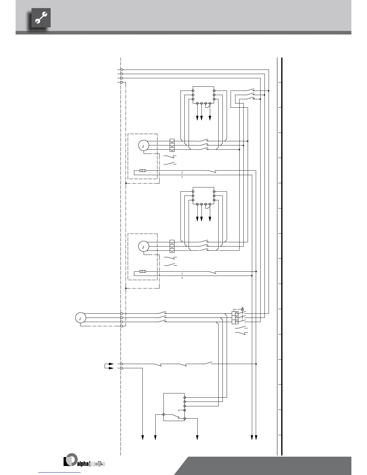
X7:7,8 Connection of external motor protection; bridge if no external motor protection can be connected.
R21
Sump heating for compressor 2
Compressor 2VD2
Motor protection switch, well / brine pump
M2
Compressor 1
Well / brine pump provided by customer
K2
Contactor, well / brine pump
VD2
Legend:
Function
F3
K1
Operating materials
K3
VD1
Mains contactor, condenserK0
VD1 Bypass contactor compressor 1
B1
X7
M3
3~PE/400V/50Hz
UK817329
3~PE/400V/50Hz
Overload relay for compressor 1
N1
F4
1
MOT
MOT
F5
N2
Starting current limit compressor 2
Starting current limit compressor 1
Bypass contactor compressor 2
BOSUP
Terminal strip in switchbox of heat pump; N/PE distribution for external 230V units
Power supply compressor; right-hand rot. field is mandatory!
1
2
Phase sequence relay; if phase sequence in the order of 11 + 14 is closed
Sump heating for compressor 1
Overload relay for compressor 2
R20
M1
2
We reserve the right to make technical changes.
UK830509/200114 © Alpha-InnoTec GmbH
SWP 540 – SWP 820 · SWP 330H – SWP 500H Circuit Diagram 1/3
 Loading...


