AC power input
The AC power connector is located on the rear panel with the fuses
located in the receptacle. Check the ratings on the fuse for the correct
ratings, and only install replacement fuses with the correct rating. A six
(6) foot modular power cable is supplied with each instrument
Power Switches
The power switch is located on the rear of the Series 800 TEC
Controller. The Series 850 TEC Controller has the power switch located
on the front panel.
Connecting the Sensor Input Connector
The first connection to make is the sensor mating connector. The wiring and
controller setup procedure is detailed in the next section of this manual
(Section 4.0).
Locate the sensor input mating connector supplied with the instrument labeled
SENSOR and push the sensor mating connector into the 3 holes. The connector is
polarized - one pin is larger than the other two, and allows three connections to be
made between the sensor and the instrument. To access the screw terminals simply
remove the cover to expose the terminals of the connector.
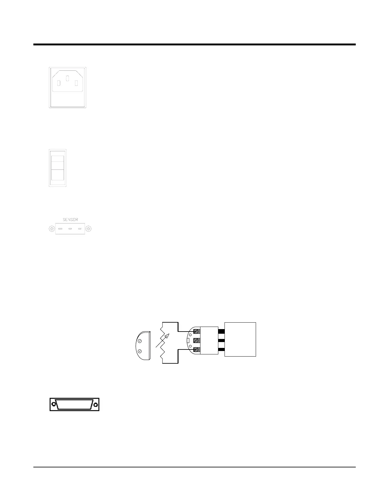
This is a pictorial of the connector looking down while connected into the SENSOR
input connector of the TEC controller. The connector is shown partially engaged to
show the larger polarizing terminal. A thermistor is show here as an example.
NEG
POS
GND
Thermistor
Mating Connector
Cover
TEC
Controller
Optional GPIB Interface Connector
See Appendix I for more information on the GPIB Interface.
ALPHA OMEGA INSTRUMENTS CORP. Instruction Manual
Series 800/850 Thermoelectric Cooler Controller Page 12
Fuse(s)
 Loading...