CHANGING THE GPIB ADDRESS
Default address of 04. Configuring the controller for a new address:
1. Connect the Series 850 TEC Controller to the GPIB bus controller. Note: disconnect
other equipment that may conflict with the existing address!
2. You can verify the address by simply turning the Series 850 TEC Controller OFF and
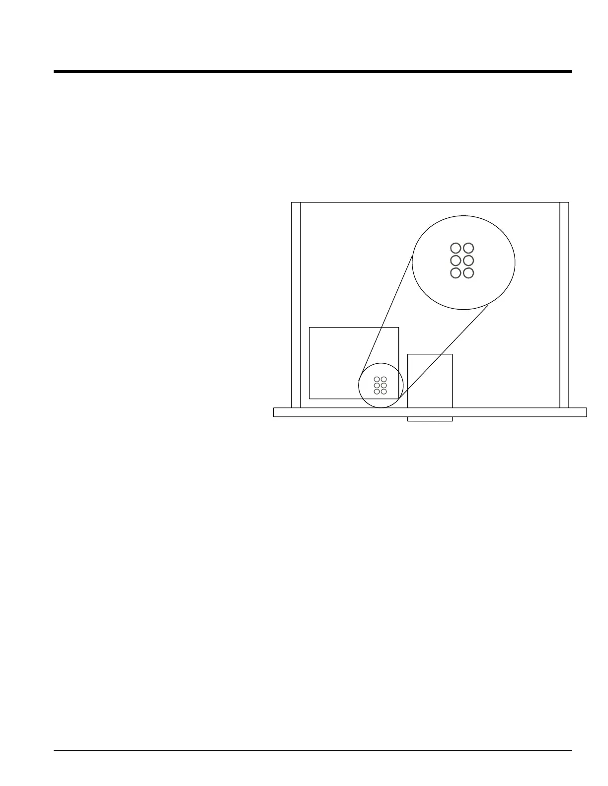
then back ON. As the Series 850 TEC Controller powers up, look at the interface
board from the top. The address will be displayed by blinking LED’s on the interface
board. Simply add the numbers in
the circles that are blinking while
powering up to determine the
address currently stored in memory.
3. Verify communication to the
controller by sending the “*IDN?”
query and read back the controller’s
IDN message.
4. To set or query the GPIB address
simply use the SCPI command:
SYST:COMM:GPIB:ADDR
5. Save the configuration using
standard IEEE-488.2 command:
*SAV 0
GBIP - COMMUNICATIONS SWITCH
For those instruments equipped with the GPIB interface, a communications port is
available to facilitate communications with the Series 850 when GPIB is not being used.
The default port type is RS-232/D, and the communications signals are present on the
DB-9 connector below the GPIB connector. The factory installed RS-232/D can be
replaced with RS-485 at the factory if specified by the customer at time of order.
There is a two position switch mounted just to the right of the DB-9 connector which
selects the source of the control signals to the Series 850 controller. When the switch is in
the UP position, the GPIB device supplies control signals to the controller. When in the
DOWN position, the serial communications port supplies control signals to the controller.
ALPHA OMEGA INSTRUMENTS CORP. Instruction Manual
Series 800/850 Thermoelectric Cooler Controller Page 90
GPIB Address
LED's
GPIB
Interface
board
RDY
LS T
FU LL
PW R
TLK
BSY
RDY
LS T
FU LL
PW R
TLK
BSY
16
8
4
21
 Loading...