dipswitch 5 is used. When more than one RO module is programmed to the same address, make sure the
dipswitch of one of the RO modules is set to ON (reply) and that the dipswitches of the other RO modules
are set to OFF (do not reply).
The output activating time can be set for each RO module separately. For the small RO module dipswitches
6 and 7 are used:
dipswitch 6 dipswitch 7 time
OFF OFF 2 seconds
OFF ON 4 seconds
ON OFF 6 seconds
ON ON 8 seconds
Dipswitch 8 is used to set the baud rate. This dipswitch is meant for future expansions and has no
function yet. With the large RO module (with power supply), dipswitch 8 isalso used to set the
activating time.
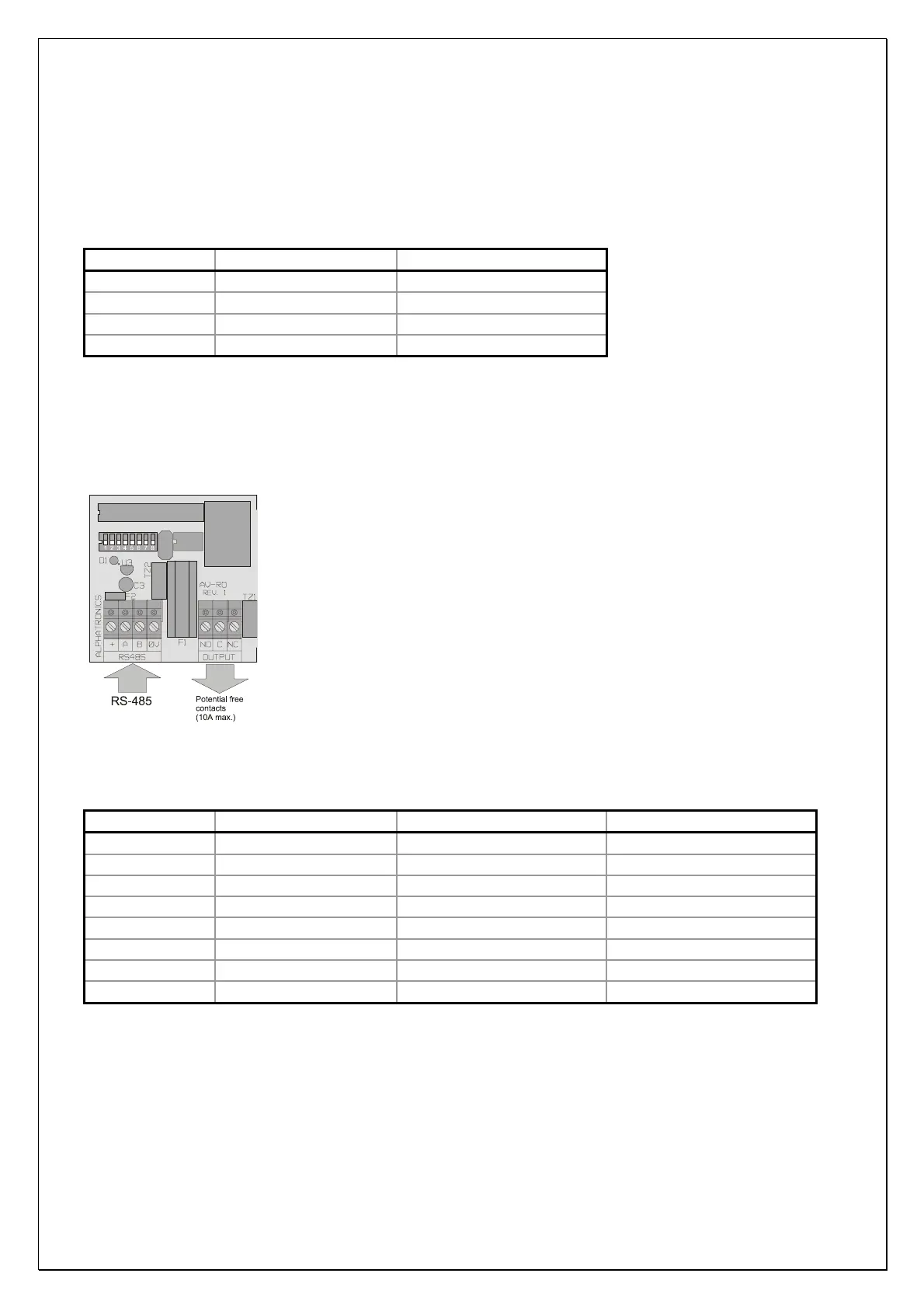
Figure 11. Wiring diagram RO (relay output) module
Use the following table for the activating time of the large RO module:
dipswitch 6 dipswitch 7 dipswitch 8 time
OFF OFF OFF 2 seconds
ON OFF OFF 4 seconds
OFF ON OFF 8 seconds
ON ON OFF 12 seconds
OFF OFF ON 16 seconds
ON OFF ON 24 seconds
OFF ON ON 32 seconds
ON ON ON 64 seconds
AlphaVision NG installation manual Rev. 2.0 27-08-2003 Blz. 21/101