CAUTION: Holding the nut with one hand and turning the
lever, like a regular bolt, with the other hand will not clamp the
wheel in the frame or fork securely. To securely clamp the wheel,
the full pivoting force of the quick release lever is required.
Quick release skewer mechanism set-up
The wheel hub is locked in the bicycle frame or fork by the quick
release tightening force on the one end and by the tension adjusting
nut on the other end. This force is controlled by turning the tension
adjusting nut. By turning the nut clockwise while keeping the quick
release skewer stationary, the tightening force is increased; by
turning the nut counterclockwise the tightening force is reduced.
Less than half a turn of the tension adjusting nut can reduce the
tightening force from sufficient to a hazardous level.
2. INSTALLATION AND REMOVAL OF WHEELS WITH QUICK
RELEASE SKEWERS
А. Front wheel removal
1. If your bicycle uses V-brakes, disconnect them so that the tyre
can pass between the pads (see section 5.1.C, fig. 12-15).
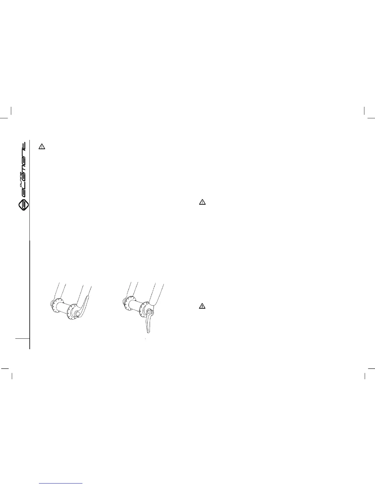
2. Turn the quick release lever from the CLOSED position to the
OPEN position (fig. 8а and 8b). 3. Loosen the tension adjusting nut
by approximately six full turns. This will prevent the quick release
skewer catching on the brake bosses, preventing the wheel from
dropping out. If there are no bosses, additional loosening of the nut
is not required.
4. Raise the front end of the bicycle 10–15 cm off the ground and
tap the wheel gently out of the fork dropouts.
B. Front wheel installation
ATTENTION: If your bicycle is equipped with disc brakes,
take care not to damage the disc, brake pads, or the calliper
when reinstalling the wheel. Never press the disc brake lever,
unless the disc is properly inserted into the calliper.
1. Put the quick release lever in the OPEN position (fig. 8b).
2. Reinstall the wheel and make sure that the hub axle is properly
seated in the fork dropouts. The quick release lever should be
located on the left side of the bicycle.
3. Holding the quick release lever in the OPEN position with your
right hand, install the tension adjusting nut with your left hand, so
that the clearance between the fork and the nut on the one end,
and the clearance between the fork and the lever on the other end
is about 1–2 mm (fig. 7).
4. Pressing down on the wheel with the fork and centring it
simultaneously, turn the quick release lever to the CLOSED
position and press it parallel to the fork “leg.”
WARNING: Apply considerable pressure to lock the
wheel securely in place. If you can fully “close” the quick
release lever without clasping your fingers around the forkleg
to increase the tightening force, and the lever does not clearly
imprint itself on your palm, the tightening force is insufficient
(fig. 8а, fig. 8b). “Open” the lever, turn the tension tightening
nut clockwise by a quarter of a turn and try again.