3.6 System description
Note: storage temperature sensor T3 is optional sensor, if this sensor is not installed on the
upper part of the storage, controller will adopt the temperature signal from sensor T2
installed on the bottom part of storage to control back-up heater or circuit pump.
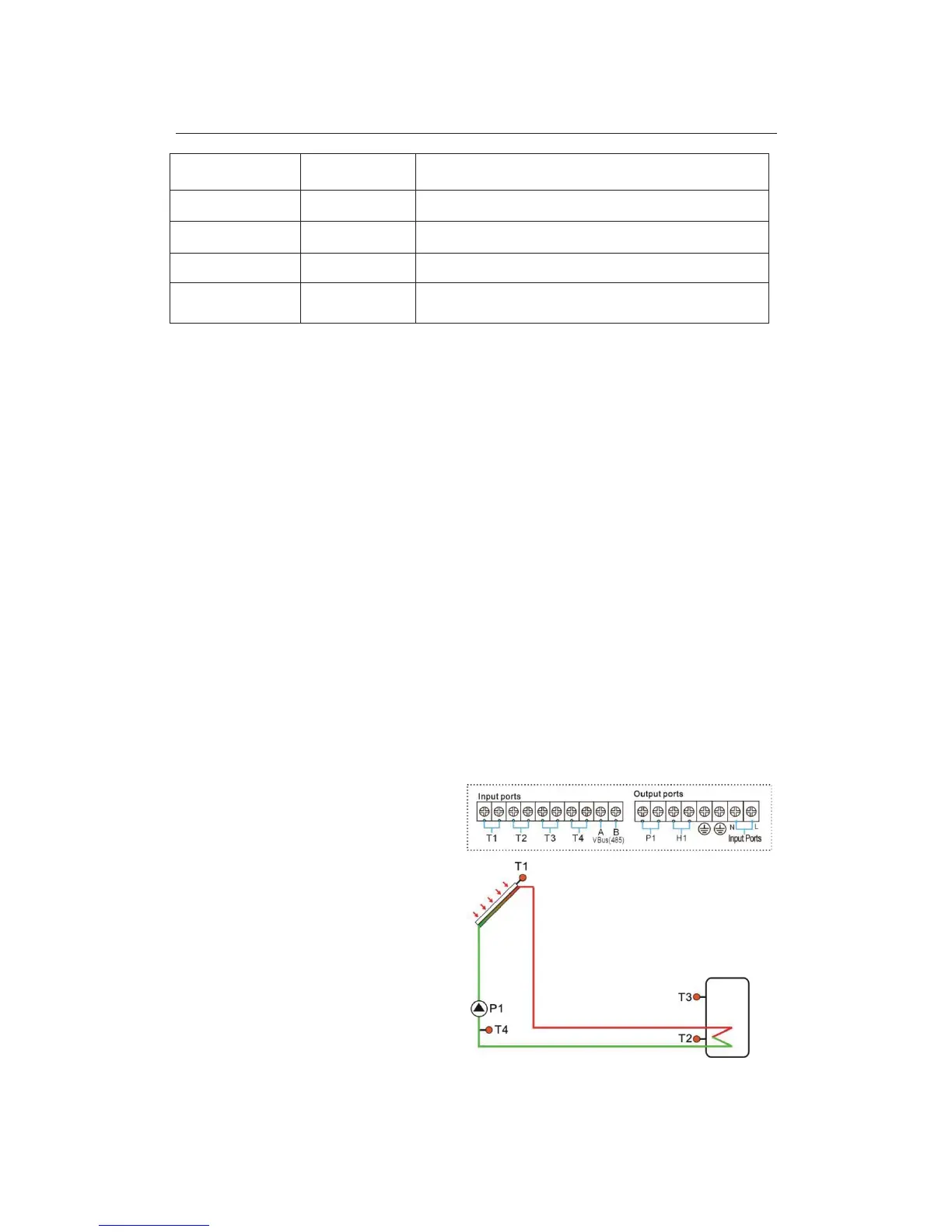
1 collector array- 1tank -1 circuit pump-back-up heater
System description:
Controller compares the temperature between collector T1 and storage T2 ( bottom part), if
the temperature difference ˄DT˅ rises up to the preset switch-on (ΔT1)or is over it, circuit
pump P1 is triggered , and then storage is heated until DT drops to the switch-off DT or
when the storage temperature T3 rises up to its preset maximum temperature. Then circuit
pump P1 is ceased.
Back-up heating: ( see details at tHET timing heating menu)
With the preset heating time section, if tank temperature (T3) drops to the switch-on
temperature of heating, then back-up heat resource H1 is triggered automatically, when
tank temperature T3 rises up to the preset switch-off temperature, then output H1 is ceased.
T1: Temperature sensor on collector
T2: Temperature sensor on the bottom
part of tank
T3: Temperature sensor on the top part
of tank (optional)
T4˖Sensor for thermal energy
measuring function, installed on the flow
pipe to collector(not included within
delivery scope)
P1: Solar circuit pump
H1˖Back-up heater