SR1128 operation manual
~6~
1 x RS485 remote control connection
x Outputs˖1 PWM output˄≤200W˅; 1 relay output ( each available power≤300W˅
x Ambient temperature˖-10-50
o
C
x Water proof grade˖IP40
Note: SD card isn’t included within the delivery scope of controller.
3. Installation
Controller can only be installed indoors, far away from dangerous place and away from the
electromagnetic field.
3.1 Installing controller
Note: the controller can only be mounted in an area having an adequate level of protection.
► Determine the mounting site of controller.
► Drill the upper fixing hole on the wall.
► Fasten a screw.
► Move the terminal cover
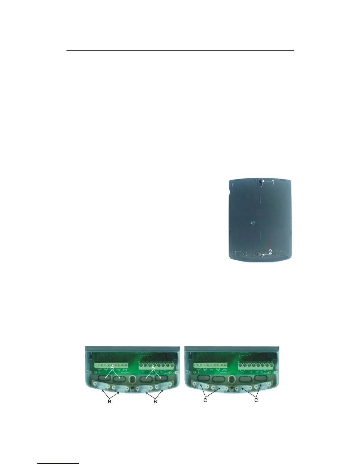
► Hang the base plate on the position ķ( showed in picture)
► Mark the position of 2 bottom holes ĸ
► Remove the base plate
► Drill the bottom fixing hole
► Re-hang the base plate on screw ķ
► Fasted screw on ĸ and fix base plate.
3.2 Wire arrangement
Depending on the type of installation, the cables may enter the controller through the rear
hole of the case A or the lower side hole of the case B.
Cable comes from the rear hole A: Remove the plastic flaps from the rear side of the case
using an appropriate tool.
Cable comes from the below hole B: Cut the left and right plastic flaps using an
appropriate tool (e.g. knife) and break them out of the case.
Notes: the flexible wire must be fastened on the case using the clamps C provided.