SR1128 operation manual
~35~
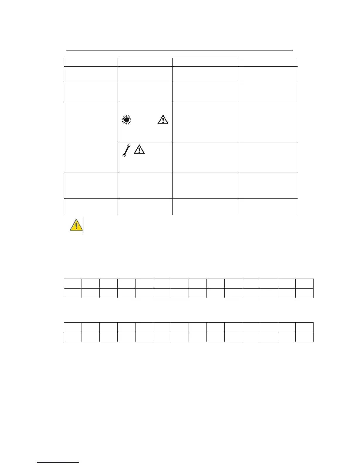
Symptoms
Controller does not
appear
Display shows nothing,
no display illumination
Controller power supply is
interrupted or program is out
of work
Check the controller power
cable
The solar pump doesn’t
operate, despite the fact
that switch
The pump symbol on the
display blinks
Pump power supply is
interrupted
Check the pump power
cable
Solar circuit pump
doesn’t operate
The pump symbol in the
display doesn’t b
The maximum storage tank
temperature (SMX1) has been
reached
The maximum collector
temperature (EM) has been
reached.
-
Error message displays
on the screen
Sensor fault (short circuit or
open circuit)
Check values of every
connected sensor; replace
all defective sensors and
/or cabling.
The solar pumps
operated, despite the
fact that the switch
on
conditions are not
satisfied
The pump symbol on the
display blinks.
Holiday function or Frost
protection function or tank
re
No problem, it is normal. If
necessary to deactivate
the corresponding
functions.
One function can’t be
activated
no function selected in
submenu
All inputs and outputs are
used; inputs and outputs can’t
be used doubly.
Warningʽ Remove the device from the mains supply before opening the case
A potentially defective sensor can be checked using an ohmmeter. To do this, the sensor
must be disconnected, its resistance measured, and the value compared with the figures in
the table below, small deviation (±1%) is acceptable.
PT1000 resistance value
NTC 10K B=3950
resistance value
9. Quality Guarantee
Manufacturer provides following quality responsibilities to end-users: within the period of
quality responsibilities, manufacturer will exclude the failure caused by production and
material selection. A correct installation will not lead to failure. When a user takes incorrect
handling way, incorrect installation, improper or crud handling, wrong connection of sensor
ć