58
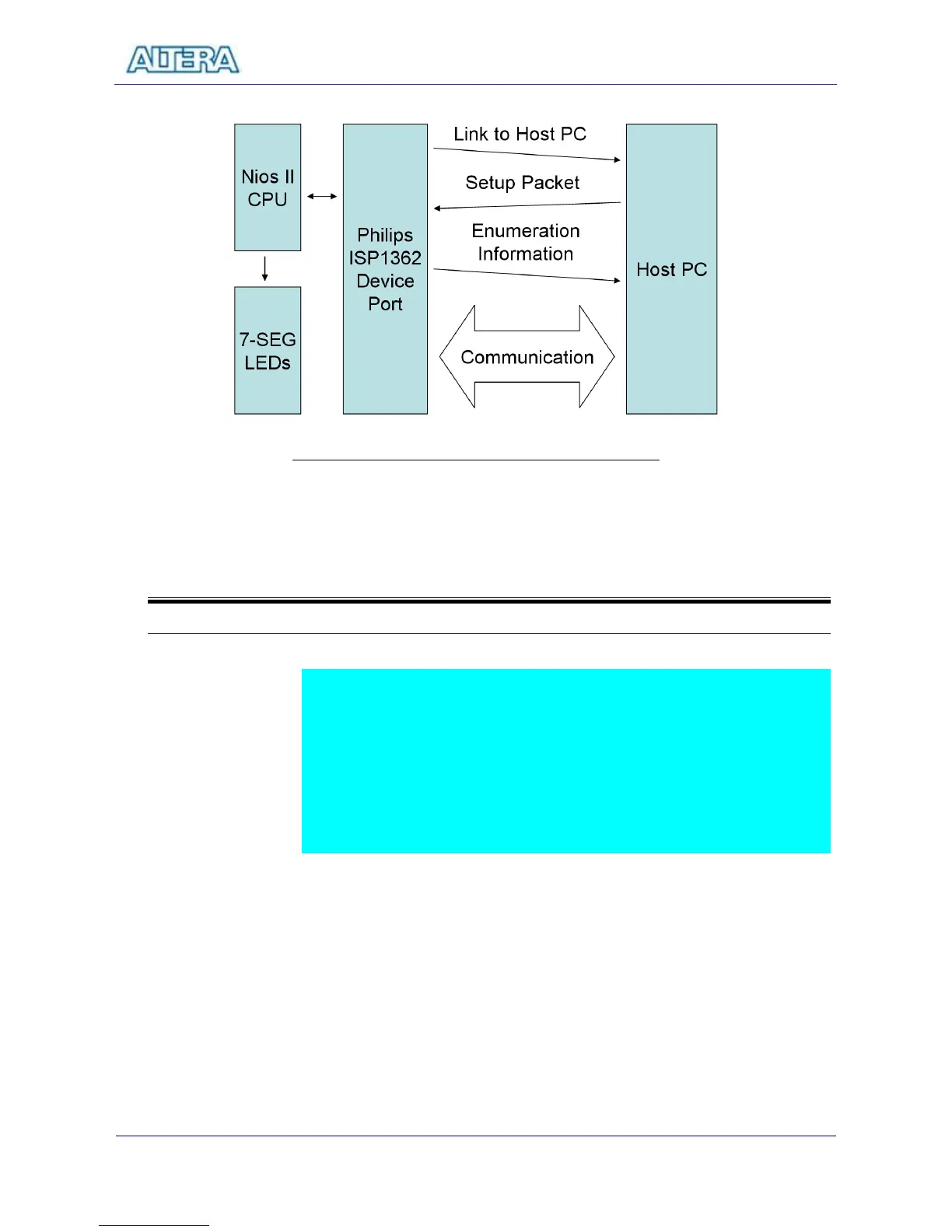
Figure 8.1 The Block Diagram of the USB Device Project
8-2
Lab Setup and Instructions
Project Directory: C:\DE2\UP4_NIOS_DEVICE_LED\DE2_ISP1362_DC
Bitstream Used: UP4_api.sof or UP4_api.pof
NIOSII Workspace: C:\DE2\UP4_NIOS_DEVICE_LED\DE2_ISP1362_DC
BC++ Software Driver: C:\DE2\UP4_NIOS_DEVICE_LED
Refer to Figure 8.2 and setup the lab according to the following steps:
Load the bitstream into FPGA
Run NIOSII IDE with DE2_ISP_1362_DC as workspace. Click on “Compile
and Run” in NIOSII IDE.
Connect the USB Device connector of the DE2 board to your PC using a
USB cable (type A->B). A new hardware (USB device) will be found.
Specify the location of the driver at C:\DE2\UP4_NIOS_DEVICE_LED\
D12test.inf. ( Philips PDIUSBD12 SMART Evaluation Board )
Ignore some warning messages during installation.
If everything goes right, you will see Philips PDIUSBD12 SMART Evaluation
Board as the device name of your DE2 board.