19
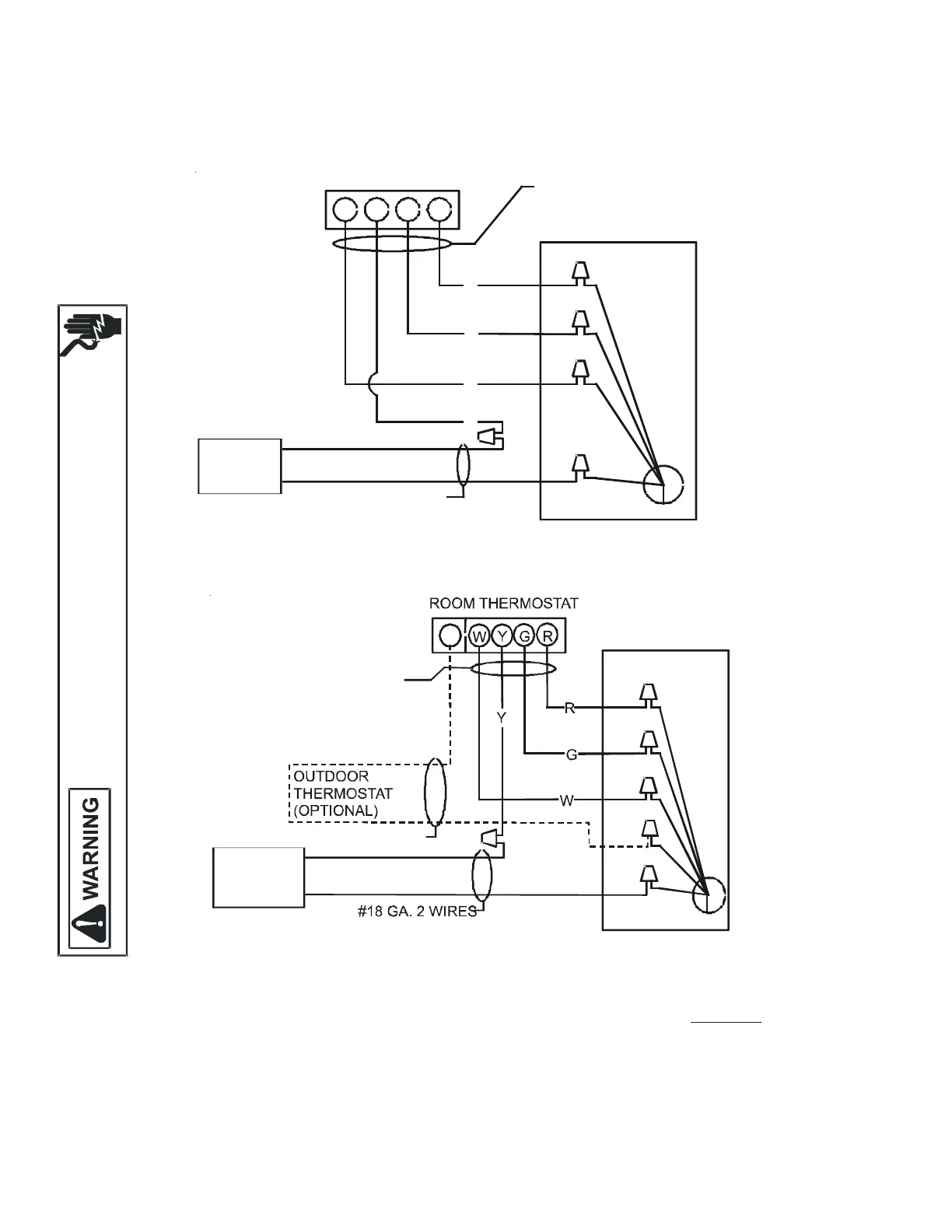
18 Wiring Diagrams
Low Voltage Wiring for ARUF Air Handlers
ROOM THERMOSTAT
W Y
G R
#18 GA. 4 WIRES WITH
COOLING 3 WIRES WITHOUT
R
G
W
Y
TO CONDENSING
UNIT 24V. CONNECTIONS
#18 GA. 2 WIRES
BLUE
WHITE
GREEN
RED
CONTACTOR
COIL
ARUF UNIT
Low Voltage Wiring Diagram for Cooling Unit with optional heat kit 10KW and below
W2
GREEN
RED
WHITE
BLUE
BROWN
#18 GA. 4 WIRE WITH
COOLING 3 WIRE WITHOUT
CONDENSING
UNIT 24V. CONNECTIONS
#18 GA. 2 WIRES
CONTACTOR
COIL
ARUF UNIT
Low Voltage Wiring Diagram for Cooling Unit with optional heat kit 15KW and above
NOTES:
1) OUTDOOR THERMOSTAT (OT-1) SHOULD BE THE
FIRST TO CLOSE AND THE LAST TO OPEN.
2) CONNECT WHITE AND BROWN WIRES FROM
AIR HANDLER TOGETHER IF OT-2 IS NOT USED.
3) REMOVE WIRE WHEN USING OUTDOOR THERMOSTAT.
NOMENCLATURE:
OT --- OUTDOOR THERMOSTAT (OPTIONAL)
EHR - EMERGENCY HEAT RELAY (OPTIONAL)
COLOR CODES
R -- RED
Y -- YELLOW
BL - BLUE
BR - BROWN
O -- ORANGE
W - WHITE
G -- GREEN
Wiring is subject to change. Always refer to the wiring diagram on the unit for the most up-to-date wiring.
HIGH VOLTAGE!
D
ISCONNECT ALL POWER BEFORE SERVICING
OR INSTALLING THIS UNIT
M
ULTIPLE POWER SOURCES MAY BE PRESENTAILURE TO DO SO MAY
CAUSE PROPERTY DAMAGEPERSONAL INJURY OR DEATH
 Loading...