20
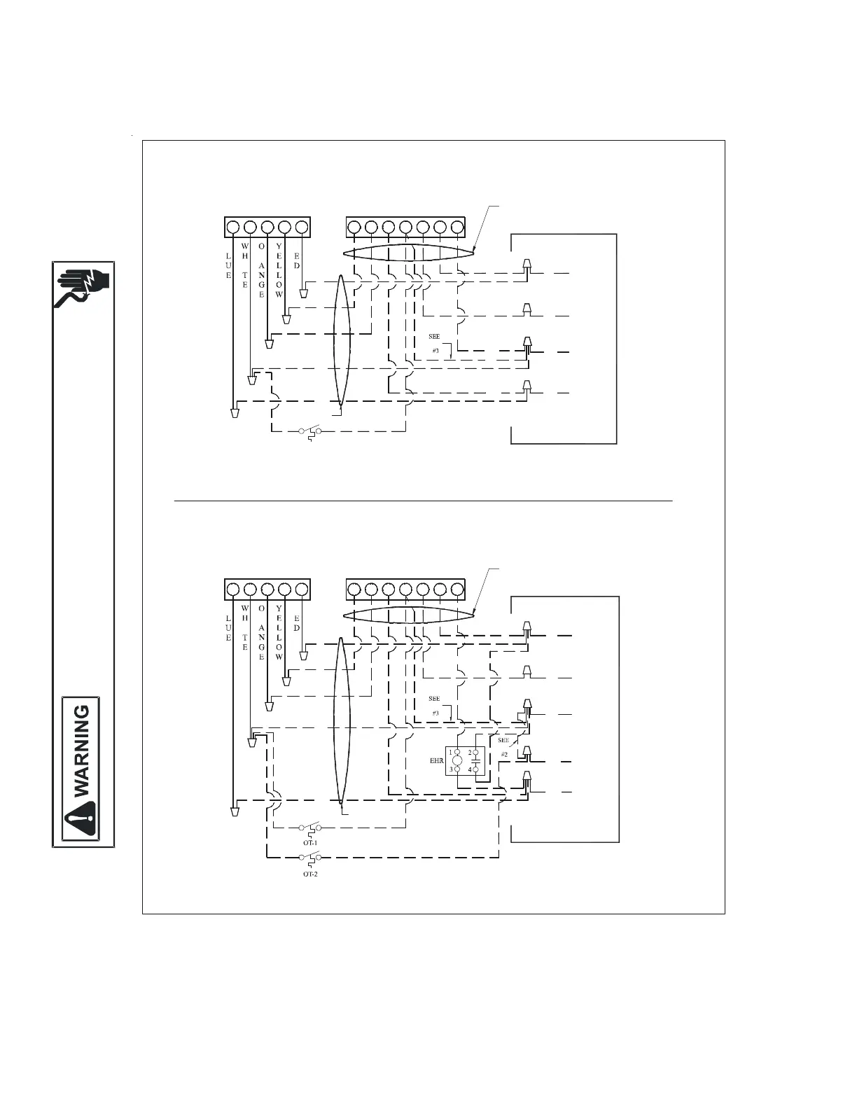
18 Wiring Diagrams
HIGH VOLTAGE!
D
ISCONNECT ALL POWER BEFORE SERVICING
OR INSTALLING THIS UNIT
M
ULTIPLE
POWER SOURCES MAY BE PRESENTAILURE TO DO SO MAY
CAUSE PROPERTY DAMAGEPERSONAL INJURY OR DEATH
Low Voltage Wiring for ARUF Air Handlers
C
W2
O Y R
YOC G R E
W2
TYPICAL H/P
ROOM THERMOSTAT
HEAT PUMP
ARUF
10 KW & BELOW
(OPTIONAL)
OUTDOOR THERMOSTAT
CLOSE ON TEMPERATURE FALL
RED
GREEN
WHITE
BLUE
AR UNIT
R
Y
O
W
BL
#18 GA. 5 WIRE
#18 GA. 7 WIRE
NOTE
R
G
BR
W
BL
R
R
I
B
#18 GA. 6 WIRE NEEDED WHEN OT IS USED
R
#18 GA. 7 WIRE NEEDED WHEN TWO OT'S ARE USED
#18 GA. 5 WIRE
BL
O
W
Y
BL
NOTE
W
G
BLUE
WHITE
GREEN
TYPICAL H/P
ROOM THERMOSTAT
ARUF
ABOVE 10 KW
HEAT PUMP
B
I
C
W2
R
YO R
R
Y CO
W2
#18 GA. 7 WIRE
RG E
R
AR UNIT
RED
BROWN
NOTE
(OPTIONAL)
OUTDOOR THERMOSTAT
CLOSE ON TEMPERATURE FALL
BR
R
G
BL
W
G
R
BL
BR
NOTES:
1) OUTDOOR THERMOSTAT (OT-1) SHOULD BE THE
FIRST TO CLOSE AND THE LAST TO OPEN.
2) CONNECT WHITE AND BROWN WIRES FROM
AIR HANDLER TOGETHER IF OT-2 IS NOT USED.
3) REMOVE WIRE WHEN USING OUTDOOR THERMOSTAT.
NOMENCLATURE:
OT --- OUTDOOR THERMOSTAT (OPTIONAL)
EHR - EMERGENCY HEAT RELAY (OPTIONAL)
COLOR CODES:
R -- RED
Y -- YELLOW
BL - BLUE
BR - BROWN
O -- ORANGE
W - WHITE
G -- GREEN
Wiring is subject to change. Always refer to the wiring diagram on the unit for the most up-to-date wiring.
 Loading...