RS1300003 Rev. 0 40 December 1997
Component Testing
Component Description Test Procedures
Freezer temperature control is a capillary
tube operating a single pole, single throw
switch.
Check for proper calibration with thermocouple capillary in air supply well buy
recording cut-in and cut-out temperatures in middle setting. See tech sheet for
model being serviced for expected temperatures.
Check control contacts are opening by disconnecting electrical leads to control
turning control knob to coldest setting and checking for continuity across
terminals.
Altitude correction must be done on both “cut-in” and “cut-out” screws.
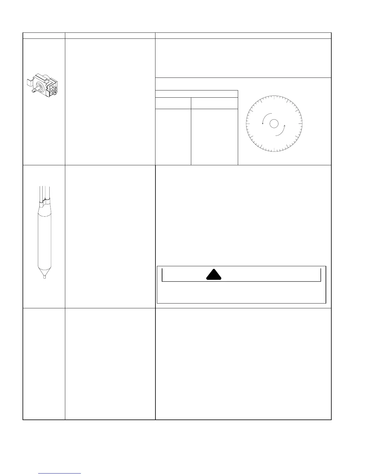
Altitude Counter in Feet
Feet Clockwise Turns
Control, freezer
temperature
(Non-electronic
units)
Altitude Adjustment
When altitude adjustment is required on
a G.E. control, turn altitude adjustment
screw 1/7 turn clockwise for each 1,000
feet increase in altitude up to 10,000
feet.
In most cases the need for altitude
adjustments can be avoided by simply
turning temperature control knob to
colder setting.
2,000
3,000
4,000
5,000
6,000
7,000
8,000
9,000
10,000
7/60
13/60
19/60
25/60
31/60
37/60
43/60
49/60
55/60
Drier Drier is placed at post condenser loop
outlet and passes liquefied refrigerant to
capillary.
Desiccant (20) 8 x 12 4AXH - 7 M>S> -
Grams
Drier must be changed every time the system is opened for testing or
compressor replacement.
NOTE:
Drier used in R12 sealed system is not interchangeable with
drier used in R134a sealed system. Always replace the drier with Amana
part number B2150504.
Before openin
refri
eration s
stem, recover HFC134a refri
erant for safe
disposal.
Cut drier out of system using the following procedure. Do not unbraze drier.
Applying heat to remove drier will drive moisture into the system.
1. Score capillary tube close to drier and break.
2. Reform inlet tube to drier allowing enough space for large tube cutter.
3. Cut circumference of drier 1 ¼
″
below condenser inlet tube joint to drier.
4. Remove drier.
5. Apply heat trap paste on post condenser tubes to protect grommets from
high heat.
6. Unbraze remaining part of drier. Remove drier from system.
7. Discard drier in safe place. Do not leave drier with customer. If refri
erator is
under warranty, old drier must accompany warranty claim.
Evaporator Inner volume of evaporator allows
liquefied refrigerant discharged from
capillary to expand into refrigerant gas.
Expansion cools evaporate tube and fin
temperature to approximately -29
°
C
(-20
°
F) transferring heat from freezer
section to refrigerant.
Passing through suction line to
compressor, the refrigerant picks up
superheat (a relationship between
pressure and temperature that assures
complete vaporization of liquid
refrigerant) as result of capillary in
suction line.
Refrigerant gas is pulled through suction
line by compressor to complete the
refrigerant cycle.
Test for leaks in evaporator with electronic leak detector or with soap solution.
Compressor oil is circulated with refrigerant; check for oil when checking for
leaks.
For minute leaks
1. Separate evaporator from rest of refrigeration system and pressurize
condenser up to a maximum of 9.65 bars (140 PSI) with a refrigerant and
dry nitrogen combination.
2. Recheck for leaks.
CAUTION
To avoid death or severe personal injury, cut drier at correct location.
Cutting drier at incorrect location will allow desiccant beads to scatter. If
spilled, completely clean area of beads.
00
5
10
15
20
25
30
35
40
45
50
55
 Loading...