RS1300003 Rev. 0 42 December 1997
Component Testing
Component Description Test Procedures
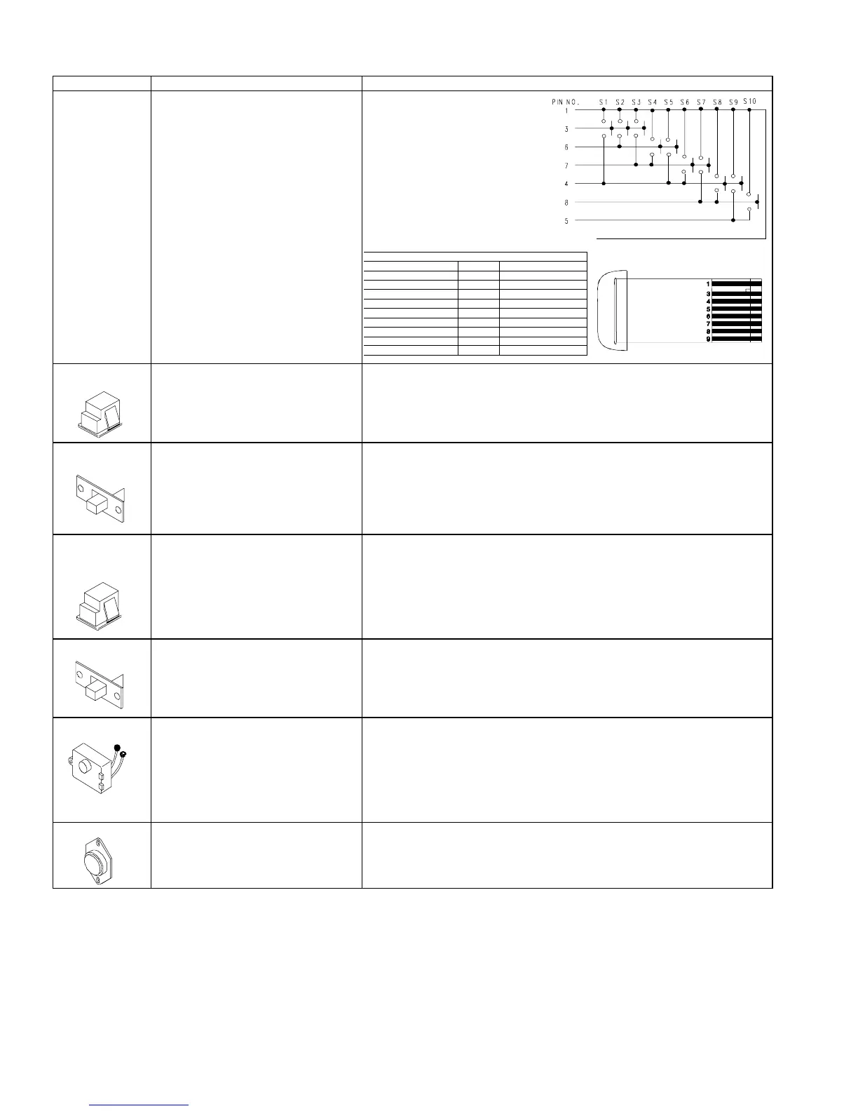
Switch, ke
board Semiconductor switch for control panel
keyboard.
Switch, SPDT
icemaker interlock
Interrupts connection to auger motor and
icemaker when freezer door is open.
Turns freezer light on when door is open.
In series with auger motor and
cube/crushed switch and freezer light.
Check resistance across terminals.
Continuity across terminals 1 and 2 – light
Continuity across terminals 1 and 3 – auger motor
Switch,
crushed/cubed
Selects between cubed or crushed ice
feature.
Check resistance across terminals.
Switch left
Middle terminal to left terminal 0 ohms
Middle terminal to right terminal infinite ohms
Switch right
Middle terminal to right terminal 0 ohms
Middle terminal to left terminal infinite ohms
Switch,
refrigerator light,
freezer light
Completes circuit to allow indicated
function. See technical data sheet and
wiring diagram for individual switch.
Check resistant across terminals.
Switch arm down
“NC” terminals Closed
“NO” terminals Open
Switch arm up
“NC” terminals Open
“NO” terminals Closed
Switch, power Disconnects all power to unit when
switch if off (open.)
Unit shipped with switch on.
Check resistance across terminals
Switch,
photosensitive
In series with cavity light switch and
cavity light. Senses low light condition to
complete circuit to cavity light.
Switch must not generate line conducted
noise or radiate inference more than
three feet on the AM, FM, VHF, or USH
Frequency bands.
1. To check light sensor with cavity light switch on, cover light sensor eye.
Cavity lamp should light at approximately 50% of full illumination.
2. If lamp fails to illuminate, activate water or ice dispenser switch. Lamp
should illuminate at full illumination and water or ice should be dispensed.
3. If light illuminates, disconnect power and replace light sensor.
4. If lamp does not illuminate, disconnect power and check cavity lamp and
socket.
Thermistor Senses temperatures within refrigerator
and freezer compartments.
Check resistance across terminals. See technical data sheet for bell curve
resistance chart at given temperatures.
PERIMETER
STATIC GUARD
Switch Functions
Enable Key S1 S1 and Pin #3 and #4
Freezer Temperature S2 S2 and Pin #3 and #6
Refri
erator Temperature S3 S3 and Pin #3 and #7
Warmer S4 S4 and Pin #6 and #7
Colder S5 S5 and Pin #4 and #6
Vacation S6 S6 and Pin #4 and #7
Max Cool S7 S7 and Pin #7 and #8
Fast Freeze S8 S8 and Pin #4 and #5
Alarm Off S9 S9 and Pin #4 and #8
Displa
Off S10 S10 and Pin #5 and #8
 Loading...