D-39
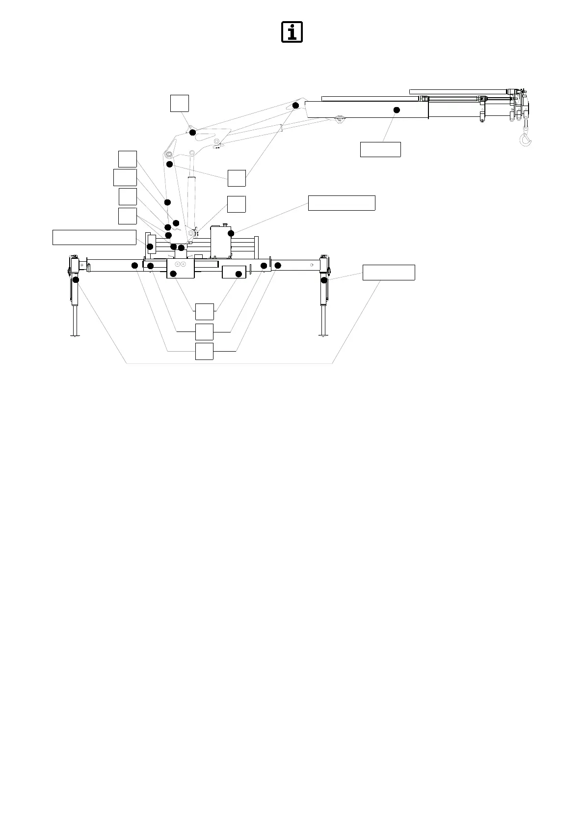
SCHEMA DI POSIZIONAMENTO DEI
PITTOGRAMMI
DESCRIZIONE DEI PITTOGRAMMI
5 - Non inserire gli arti inferiori sotto le
aste stabilizzatrici durante l’operazione
di stabilizzazione (§A.1.2)
12 - N
on sostare nelle vicinanze del
primo braccio durante le operazioni di
apertura e chiusura della gru (§A.1.4)
13 - prim
a di iniziare la procedura di
apertura gru, chiudere completamente il
2°braccio (§B.9.4)
14 - Indossar
e guanti da lavoro, scarpe
antinfortunistiche ed elmetto.
15 - pericolo di cesoiamento
(§A.1.3)
16 - pericolo di contatto con linee
elettriche (§A.2.1)
17 -
pericolo di caduta del carico
(§A.1.5)
18 - peric
olo di movimentazione carichi
sospesi (§A.1.5)
19 - Divieto di indirizzare getti d’acqua
(§A.9, §C.2.4)
20
- Posizionamento attacco gancio per
sollevamento gru
21 - Posizionamento punto morto gru
22 - Allineamento colonna in posizione
di chiusura
23 - Tensione di alimentazione gru
24 - Completa estensione aste stab.
(§A.1.7)
25 - Punti di appoggio forche per
sollevamento gru
26 - Divieto di operare in atmosfera
potenzialmente esplosiva.
(*) - Pittogrammi per optional
POSITIONING DIAGRAM OF
PICTOGRAMS
DESCRIPTION OF DECALS
5 - Do not insert lower limbs under
stabiliser rods during stabilisation
(§A.1.2)
12 -
Do not approach the first boom
during crane opening and closing
(§A.1.4)
13 - Cl
ose the 2nd boom completely
before starting the crane opening
procedure (§B.9.4)
14 - W
ear gloves, helmet and industrial
footwear during crane operation
15 - Cutting hazard (§A.1.3)
16 - Po
wer line electric shock hazard
(§A.2.1)
17 - Load fall hazard (§A.1.5)
18 - Sus
pended load movement hazard
(§A.1.5)
19 - Do NO
T use water jets (§A.9,
§C.2.4)
20 - Hook attachment to lift crane
21 - Crane dead point position
22 - Alignement points of the column in
closed position
23 - Crane power supply voltage
24 - Full extension of the stabilizer rod
(§A.1.7)
25 - F
ork support positions to lift crane
26 - Do NOT operate in potentially
explosive atmospheres.
(*) - Pictograms for optionals
AUFSTELLUNGSDIAGRAMM DER
PIKTOGRAMME
BESCHREIBUNG DER PIKTOGRAMME
5 - Die unteren Gliedmaßen während
der Stabilisierung nicht unter die
Abstützstangen bringen (§A.1.2)
12 - Be
im Aus- und Einfahren des
Krans nicht in der Nähe des
1.Auslegers verweilen (§A.1.4)
13 - Bevor
mit dem Ausfahren des
Krans begonnen wird, muss der
2.Ausleger vollständig eingefahren
werden (§B.9.4)
14 - Arbeitshandschuhe, Sicherheits-
schuhe und Schutzhelm tragen.
15 - Schergefahr (§A.1.3)
16 - G
efahr durch Kontakt mit elektri-
schen Leitungen (§A.2.1)
17 - Gefa
hr durch Herabfallen der Last
(§A.1.5)
18 - Gefahr durch Beförderung schwe-
bender Lasten (§A.1.5)
19 - Verbot, Wasserstrahlen auf die
Maschine zu richten (§A.9, §C.2.4)
20 - Positionierung der Transportöse
zum Anheben des Krans mit Haken
21 - Positionierung des Totpunkts
22 - Richtpunkte der Säule in
Ruhestellung
23 - Versorgungsspannung des Krans
24 - Völliges Ausfahren der Abstutz-
stangen (§A.1.7)
25 - Ans
atzstellen der Gabeln zum
Anheben des Krans
26 - Es ist verboten, in explosions-
fähiger Atmosphäre zu arbeiten.
(*) - Piktogramme für Zubehöre
1-2*-3-4-11
5*
25
24
26
6-7-8-12-14
21
15
20
6-7-10-13-19*-23
22
8-9
14
16-17-18