B-13
B.4 DESCRIZIONE DEI
COMANDI
B.4.1 PANNELLI DI
CONTROLLO GRU CE NO
RRS
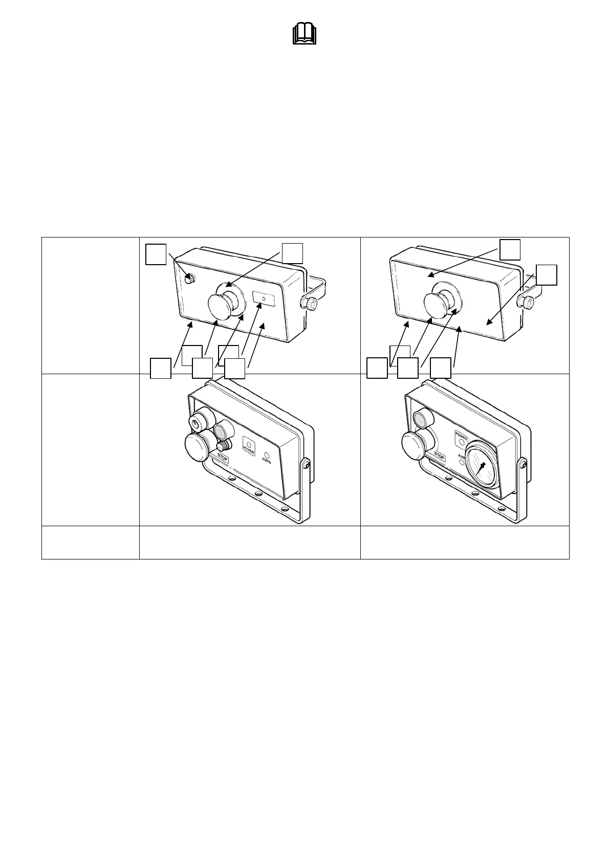
La macchina è equipaggiata di due
pannelli collocati sopra i comandi di
movimentazione sul lato destro e
sinistro della gru.
PANNELLI DI CONTROLLO
A) Chiave d'accensione
- Se ON abilita i comandi della gru.
B) Pulsante d'arresto d'emergenza
- Blocca i comandi gru (vedi §B.5.5).
C)
Spia di accensione (POWER)
- Se accesa indica impianto elettrico
abilitato.
D) Spia malfunzionamento impianto
elettrico
- Se accesa indica che l'impianto
elettrico non funziona correttamente.
E) Tasto di reset
- Sblocca la macchina quando il cilindro
1.braccio è in blocco al fine corsa
senza carico.
F) Manometro
- la lancetta sul settore giallo indica il
raggiungimento del 90% della
capacità massima di sollevamento.
- la lancetta sul settore rosso indica il
raggiungimento del 100% della
capacità massima di sollevamento.
B.4 DESCRIPTION OF
THE CONTROLS
B.4.1 CONTROL PANELS ON
EC NO RRS CRANE
The machine is equipped with two
control panels located above the
operation controls on the right and left
sides of the crane.
CONTROL PANELS
A)
Starting key
- If ON, it enables the crane controls.
B) Emergency stop button
- It stops crane controls (see §B.5.5).
C)
Alimentation pilot light (POWER)
- If this is on, the electrical system is
enabled.
D) Electric system malfunction light
- If this is on, the electric system is not
working correctly.
E) Reset button
- It unblocks the machine when the
1.boom cylinder is locked at the end
of the stroke without load.
F) Pressure gauge
- If the pointer is in the yellow sector,
the 90% of the maximum lifting
capacity is reached.
- If the pointer is in the red sector, the
100% of the maximum lifting capacity
is reached.
B.4 BESCHREIBUNG
DER STEUERUNGEN
B.4.1 SCHALTTAFELN FÜR
KRAN EG NICHT RRS
Der Kran ist mit zwei Schalttafel
ausgerüstet, die ich über den
Steuerungen der Bewegungsabläufe an
der rechten und linken Kranseiten
befinden.
SCHALTTAFELN
A) Zündschlüssel
- Auf ON, werden die Steuerungen
eingeschaltet.
B) Notstopptaste
- Schaltet alle Steuerungen aus
(siehe §B.5.5).
C) Zün
dkontrolllampe (POWER)
- Hiermit wird die elektrische Anlage
eingeschaltet.
D) Störungskontrolllampe
- Signalisiert die Störung der
elektrischen Anlage
E) Rückstelltaste
- Sie gibt die Maschine frei wenn der
1.Auslegerzylinder wegen des
Hubendes blockiert ist.
F) Druckmesser
- Wenn der Zeiger im gelben Sektor ist,
ist 90% der max. Hubkraft erreicht.
- Wenn der Zeiger im roten Sektor ist,
ist 100% der max. Hubkraft erreicht.
804 CE
805 CE
Posizione
Position
Pannello lato distributore
Panel at control valve side
Schalttafel auf steuerventilseite
Pannello lato opposto distributore
Panel at opposite control valve side
Schalttafel gegenüber Steuerventilseite
C
B
B
A
C
B
D
E
B
E
C D
F