B-8
B.3.5 DISPOSITIVI DI
SICUREZZA, LIMITATORI E
INDICATORI
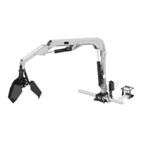
La gru è dotata di limitatori di portata,
dispositivi sicurezza e indicatori.
Tali dispositivi, elencati a seguito,
permettono all’operatore di lavorare in
sicurezza in ogni configurazione di
carico e in situazioni di emergenza. Il
loro funzionamento verrà illustrato nel
paragrafo dedicato.
L1 LIMITATORE DI MOMENTO
L2 LIMITATORE DI CARICO
PROLUNGHE MANUALI
L3 LIMITATORE DI ROTAZIONE
(OPTIONAL)
VALVOLE DI BLOCCO SUI
CILINDRI OLEODINAMICI
V1 Cilindro 1° braccio
V2 Cilindro 2° braccio
V3 Cilindro elementi telescopici
V4 Cilindri stabilizzatori
V5 Cilindri rotazione
V6 Cilindro sfilo aste stabilizzatrici
B1 BLOCCAGGIO MECCANICO
ASTE STABILIZZATRICI
B2 BLOCCAGGIO MECCANICO
PROLUNGA MECCANICA
I1 MANOMETRI INDICATORI DI
CARICO (GRU CE)
I2 TERMOMETRO OLIO (GRU
CE/RRS)
I3 INDICATORI DI LIVELLO OLIO
I4 INDICATORE DI INTASAMENTO
FILTRO OLIO (GRU CE)
I5 INDICATORI DI CARICO
LAMPEGGIANTI (GRU CE RRS)
B.3.5 SAFETY DEVICES,
LIMIT SWITCHES AND
INDICATORS
The crane is fitted with a load limit
device, safety devices and indicators.
These devices, listed below, enable the
crane to be used under safe conditions
with all load configurations and in the
event of an emergency. Functioning of
these devices is described in the
dedicated paragraph.
L1 LOAD LIMITING DEVICE
L2 MANUAL EXTENSIONS LOAD
LIMITER
L3 ROTATION LIMITER (OPTIONAL)
HYDRAULIC CYLINDER
BLOCKING VALVE
V1 1st boom cylinder
V2 2nd boom cylinder
V3 Telescopic components cylinder
V4 Stabiliser cylinders
V5 Rotation cylinders
V6 Stabiliser rod extraction cylinder
B1 STABILISER ROD MECHANICAL
BLOCK
B2 MECHANICAL EXTENSION
MECHANICAL BLOCK
I1 LOAD INDICATOR PRESSURE
GAUGES (EC CRANE)
I2 OIL THERMOMETER (EC/RRS
CRANES)
I3 OIL LEVEL INDICATOR
I4 OIL FILTER CLOGGING
INDICATOR (CE- CRANES)
I5 FLASHING LOAD INDICATOR
(EC RRS CRANE)
B.3.5 SICHERHEITSEIN-
RICHTUNGEN, BEGRENZER
UND ANZEIGER
Der Kran ist mit Lastbegrenzer,
Sicherheitseinrichtungen und Anzeiger
ausgestattet.
Diese nachstehend aufgeführten Vor-
richtungen gestatten dem Kranführer, in
jeder Ladekonfiguration und in Notsitua-
tionen sicher zu arbeiten. Ihre Funktion
wird im entsprechenden Abschnitt
beschrieben.
L1 MOMENTBEGRENZER
L2 LASTBEGRENZER DER MAN.
VERLÄNGERUNG
L3 DREHBEGRENZER (WAHLFREI)
SPERRVENTILE AN DEN
ÖLHYDRAULIKZYLINDERN
V1 Zylinder 1.Ausleger
V2 Zylinder 2.Ausleger
V3 Zylinder der Teleskopausschübe
V4 Abstützzylinder
V5 Drehzylinder
V6 Schubzylinder der Abstützstangen
B1 MECHANISCHE SPERRE DER
ABSTÜTZSTANGEN
B2 MECHANISCHE SPERRE DER
MECHANISCHEN
VERLÄNGERUNG
I1 LASTANZEIGER-
DRUCKMESSER (EG KRAN)
I2 ÖLTHERMOMETER (EG/RSS-
KRÄNE)
I3 ÖLSTANDANZEIGEN
I4 VERSTOPFUNGSANZEIGE
DES ÖLFILTERS (CE-KRÄNE)
I5 BLINKLASTANZEIGER (EG RRS
KRAN)
B1
V3
B1
B2
L1
L3
V6
L2
V1
V2
I3
I4
I1
I2
V4
V6
I5
I1
V4
V6