INSTALLATIONS
CN1: DC Jack (DC in, 12V only)
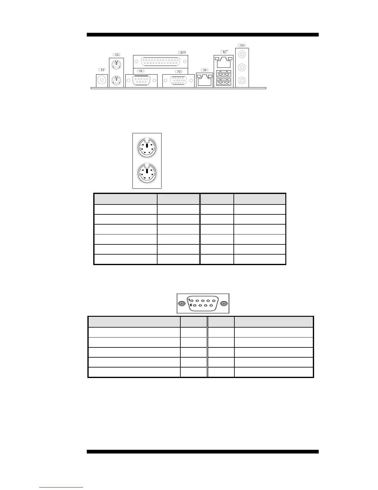
CN2: PS/2 Keyboard and Mouse Connectors
PS/2 Mouse
PS/2 Keyboard
Signal Name Keyboard Mouse Signal Name
Keyboard data 1 1 Mouse data
N.C. 2 2 N.C.
GND 3 3 GND
5V 4 4 5V
Keyboard clock 5 5 Mouse clock
N.C. 6 6 N.C.
CN3: COM1 Serial Port
CN3 (COM1) is a DB-9 connector serial port.
Signal Name Pin # Pin # Signal Name
DCD, Data carrier detect 1 6 DSR, Data set ready
RXD, Receive data 2 7 RTS, Request to send
TXD, Transmit data 3 8 CTS, Clear to send
DTR, Data terminal ready 4 9 RI, Ring indicator
GND, ground 5 10 Not Used
MB500 User’s Manual 13