Installation & Start-Up | 3-7
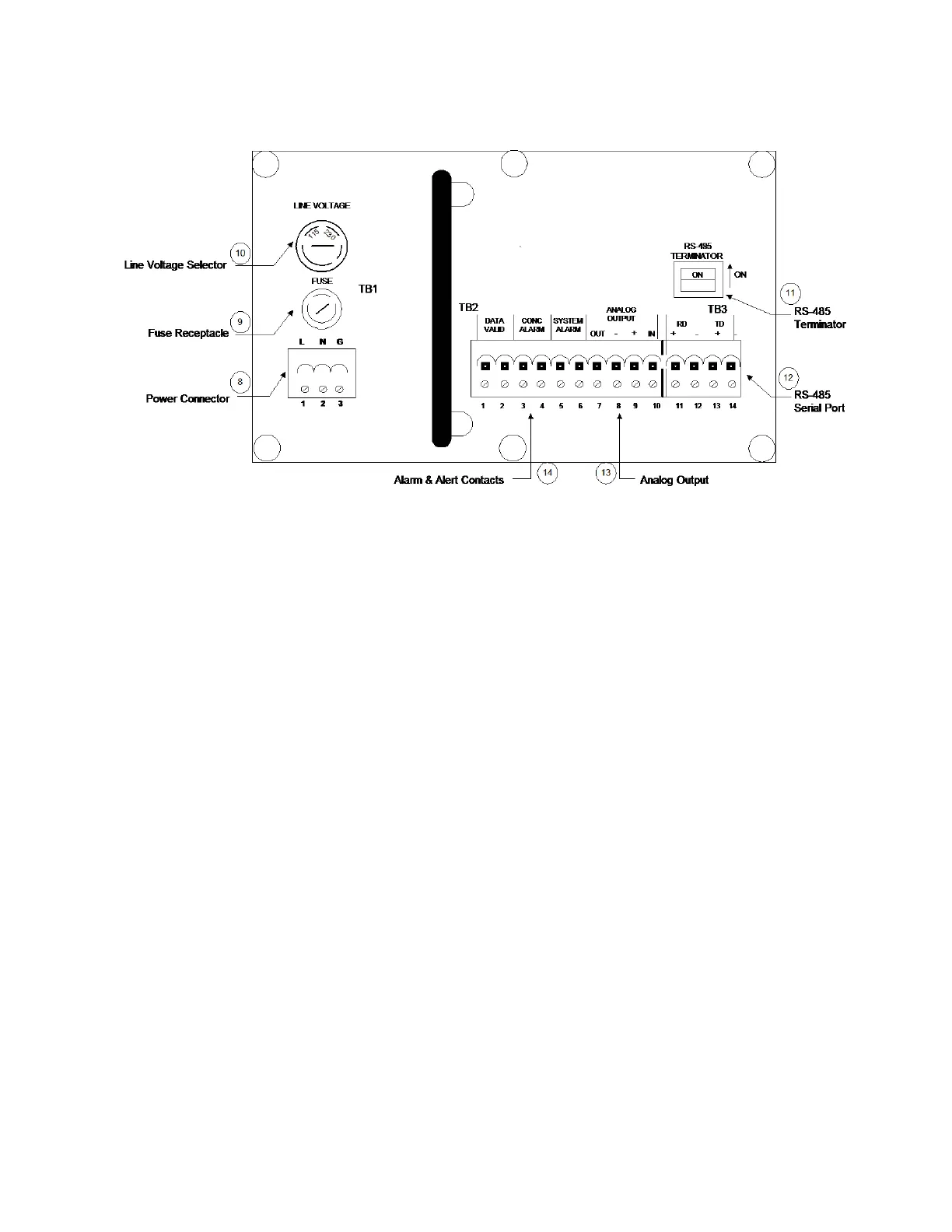
8 Power connector Connect hot (1) and neutral (2) to power
connector and ground to chassis.
9 Fuse Receptacle 2A 250V, time lag, T-type.
10 Line Voltage Selector Select 120 or 240 volt line voltage.
11 RS-485 Terminator RS-485 termination switch is on if the
analyzer is the only analyzer on line or
the last in a chain.
12 RS-485 Serial Port User serial communications interface.
Serial wiring supplied by user.
13 Analog Output 4 to 20 mA output to user recording
equipment. Wiring supplied by user.
14 Alarm Contacts Connections for: Data Valid, Concentra-
tion Alarm and System Alarm. Wiring
supplied by user.
Figure 3-3.
Model 3050 AM interface
board connections.

 Loading...