Installation & Start-Up | 3-9
6. Working with one dryer at a time to minimize the time that the de-
vice is exposed to room air, remove the first dryer from its packaging.
Loosen the 1/8 inch VCR fittings.
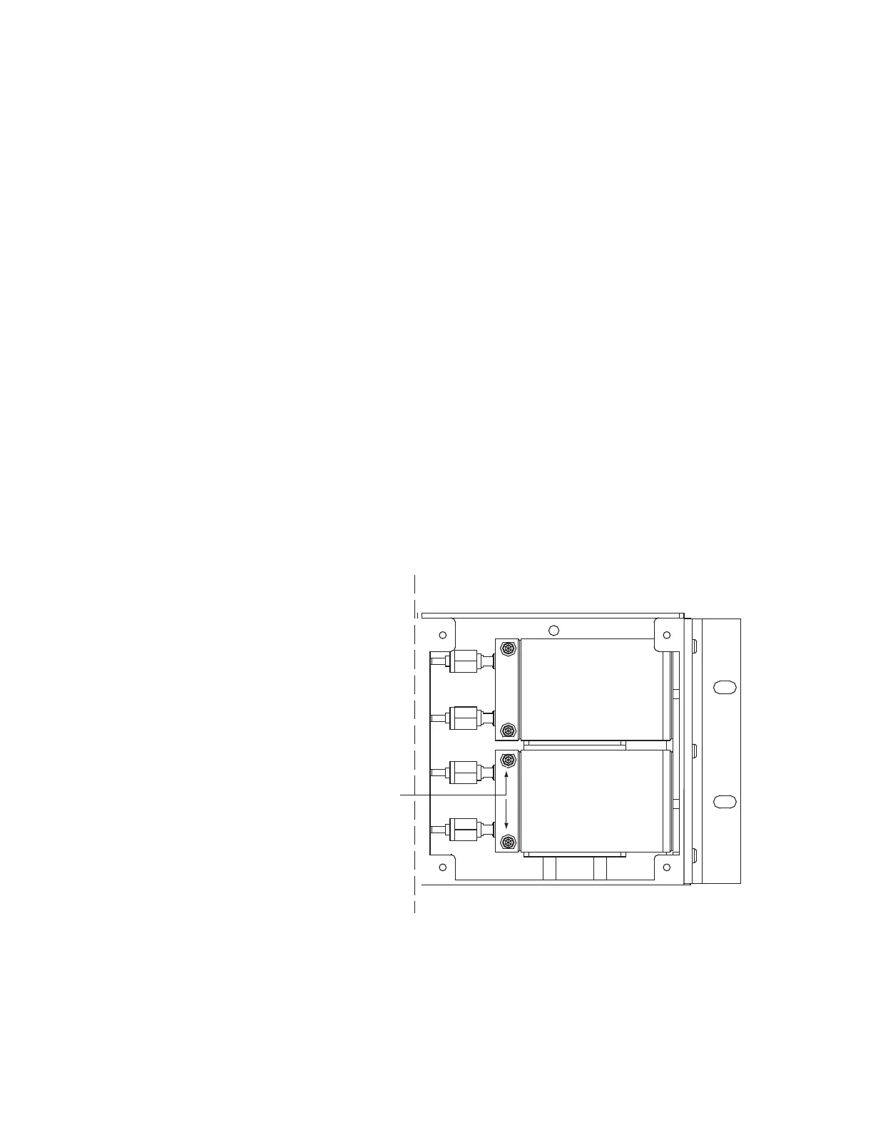
7. Using two of the dryer mounting screws, attach the dryer in the top or
sample system position (Figure 3-4b).
8. Working quickly, install a new 1/8” VCR gasket in both of the fittings,
and tighten the two VCR nuts over the fittings until they are finger
tight.
9. Tighten the nut an additional 1/8 turn.
10. Repeat steps 6 through 9 for the second dryer, which you will mount
in the bottom or zero dryer position (Figure 3-4b).
11. Replace the dryer compartment cover.
12. The production codes for the dryers supplied with the analyzers have
been entered at the factory, so there is no need to enter them during
an initial startup of the analyzer. For all subsequent replacement/in-
stallations of replacement dryers, you will need to enter a production
code for the reference dryer (see details in Chapter 4).
Figure 3-4b.
Inside dryer compartment.
Sample Syst em
Dryer
Zero Dryer
ryer Mounting Screws

 Loading...