13
IOM (Safety) - Installation, Operation and Maintenance
Optical Oxygen Analyzer
Section 3
Installation
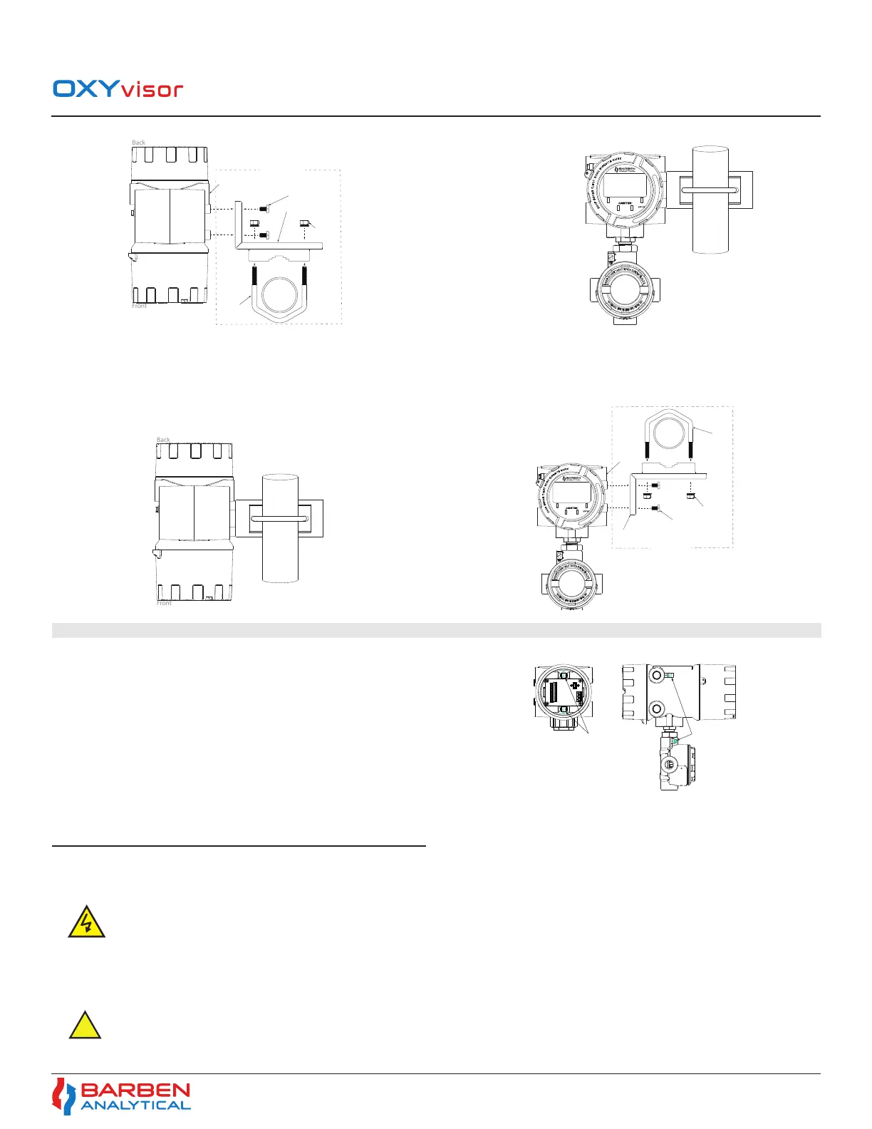
Figure 5 - OXYvisor Vertical Pipe Mount Examples
1-1/2” to
2-1/4“ pipe
or similar
(2) 316 SS
M8 Nut
316 SS
U-Bolt
(4) 316 SS M6
Slotted Screws
316 SS L-Bracket
(4) 3/4” NPT or M25x
1.5 6H Conduit Ports
VERTICAL PIPE MOUNT - TOP VIEW
316 SS Pipe
Mount Bracket
ESC
OXYvisor
1-1/2” to
2-1/4” pipe
orsimilar
Vertical Pipe Install - FRONT VIEW
1. Locate the proper height for the HMI and display so that it is easily accessible for user
2. Install the L-bracket to the analyzer by tightening down the (4) M6 slotted screws.
3. Install the U-bolt around the pipe at the proper height into the L-bracket and tighten the M8 nuts
4. Double check tightness of the screws and bolts
3�5�3 OXYvisor - Pipe-Mount to Horizontal Pipe
Horizontal Pipe Install - TOP VIEW
1-1/2” to
2-1/4” pipe
orsimilar
1-1/2” to
2-1/4” pipe
or similar
(2) M8 Nuts
(4) M6 Slotted Screws
ESC
OXYvisor
(4) 3/4” NPT
or M25x1.5
6H Conduit
Ports
316 SS Pipe
Mount Bracket
Horizontal Pipe Install - FRONT VIEW
316 SS L-Bracket
316 SS
U-Bolt
Figure 6 - OXYvisor Horizontal Pipe Mount Example
The OXYvisor can be ordered with either 120-240VAC input power
or 24VDC input power. Before connecting any electrical signal or power,
a protective ground on the analyzer enclosure must be connected.
Requirements for the Protective Ground conductor are as follows:
• The protective conductor must be of equal or greater size than any
other current-carrying wiring.
• The protective conductor must remain connected until all other
wiring is removed.
Figure (7) shows the Protective Ground screw locations.
3.6 Wiring - Power
3.6.1 Protecve Ground (Earthing) Screw
Figure 7 - OXYvisor Protective Ground Screws
Analyzer Side ViewAnalyzer Rear View
(Rear Lid Removed)
Internal Protective
Ground Screws
Ground Screws
3.6.2 AC Powered Analyzer
The OXYvisor control unit can operate using between 85-240 volts AC, 47 to 63 Hz. There is no power switch or circuit breaker on the control unit,
and it must be protected by installing it on a circuit-protected line, with recommended maximum 1 amperes, with a switch or circuit breaker in close
proximity to the control unit and within easy reach of an operator. Mark the switch or circuit breaker as the control unit disconnecting device.
Analyzer- Mains Supply Connections (AC Version)
AC Power
OXYvisor analyzers ordered with AC power input will have a termination board labeled with “Line”, “Neutral”, and “Earth” (Ground) as shown in
Figure (8).
Warning - Hazardous voltage and risk of electrical shock - make sure main power is shut o prior to attaching wiring to analyzer.
Power Supply wiring requirements:
• 24 to 12 gauge (IEC .500 to 2.00)
• Copper, stranded wire
• Minimum 300V Insulation
• Tightened (torque) to 0.5 to 0.6 Nm
 Loading...